With the rapid development of smartphones, people tend to pursue fast charging for their phones. Currently, there are two fast charging technologies: Qualcomm’s high-voltage fast charging and VOOC’s low-voltage high-current fast charging. Both fast charging methods have their own advantages. The high-voltage fast charging does not have special requirements for cable materials and has strong compatibility. In contrast, the low-voltage high-current fast charging requires manufacturers to provide dedicated cables in addition to protocol support.
Huawei was the first to apply high-voltage FCP fast charging technology to its phones. Later, Huawei adopted SCP technology, which uses a low-voltage, high-current solution. We will now test a Huawei fast-charging adapter that uses SCP technology, then begin the teardown.
The fast charger model is HW-050800C1WH. The output specifications are 5V/2A and 5V/8A.
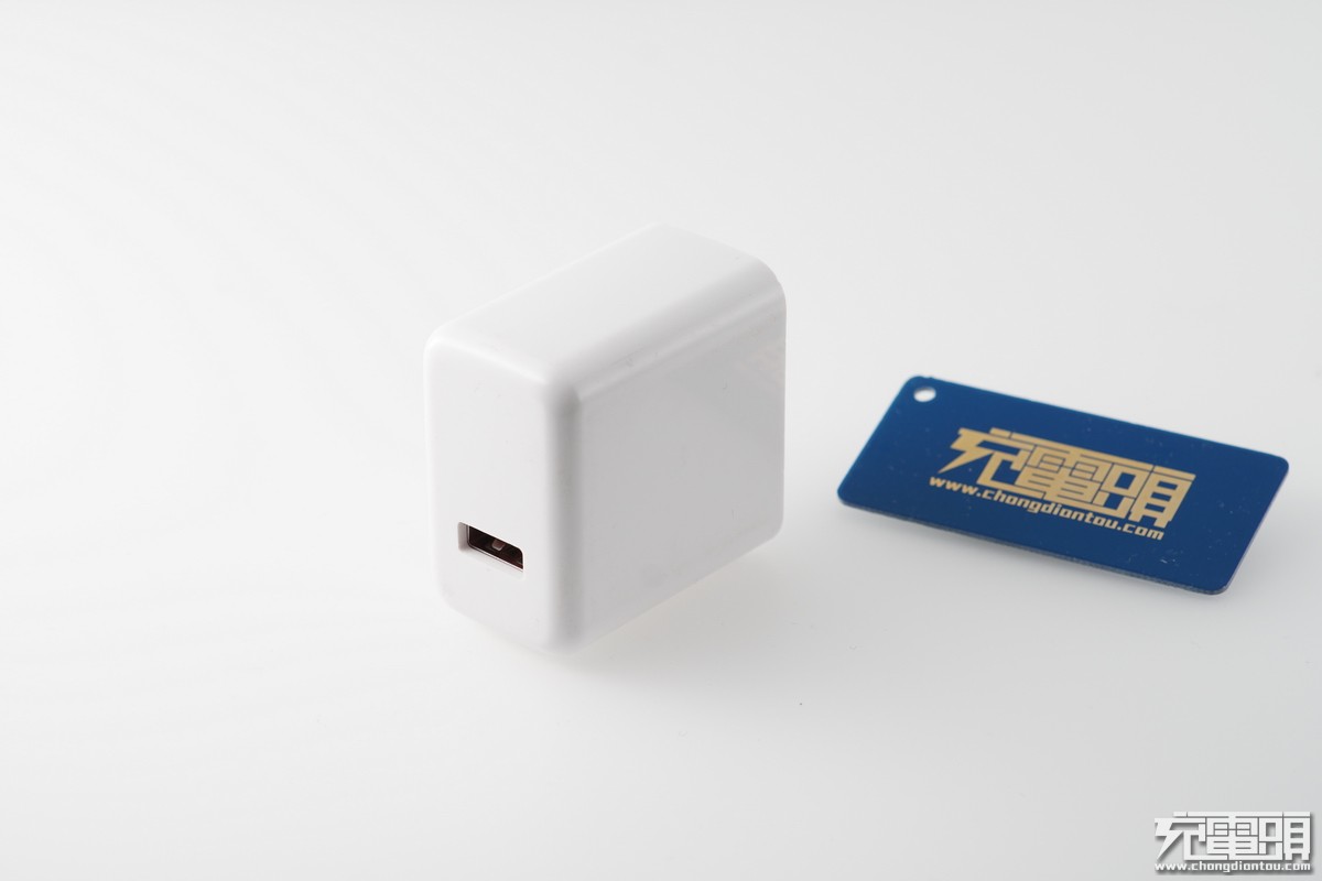
The fast charger has a white shell.
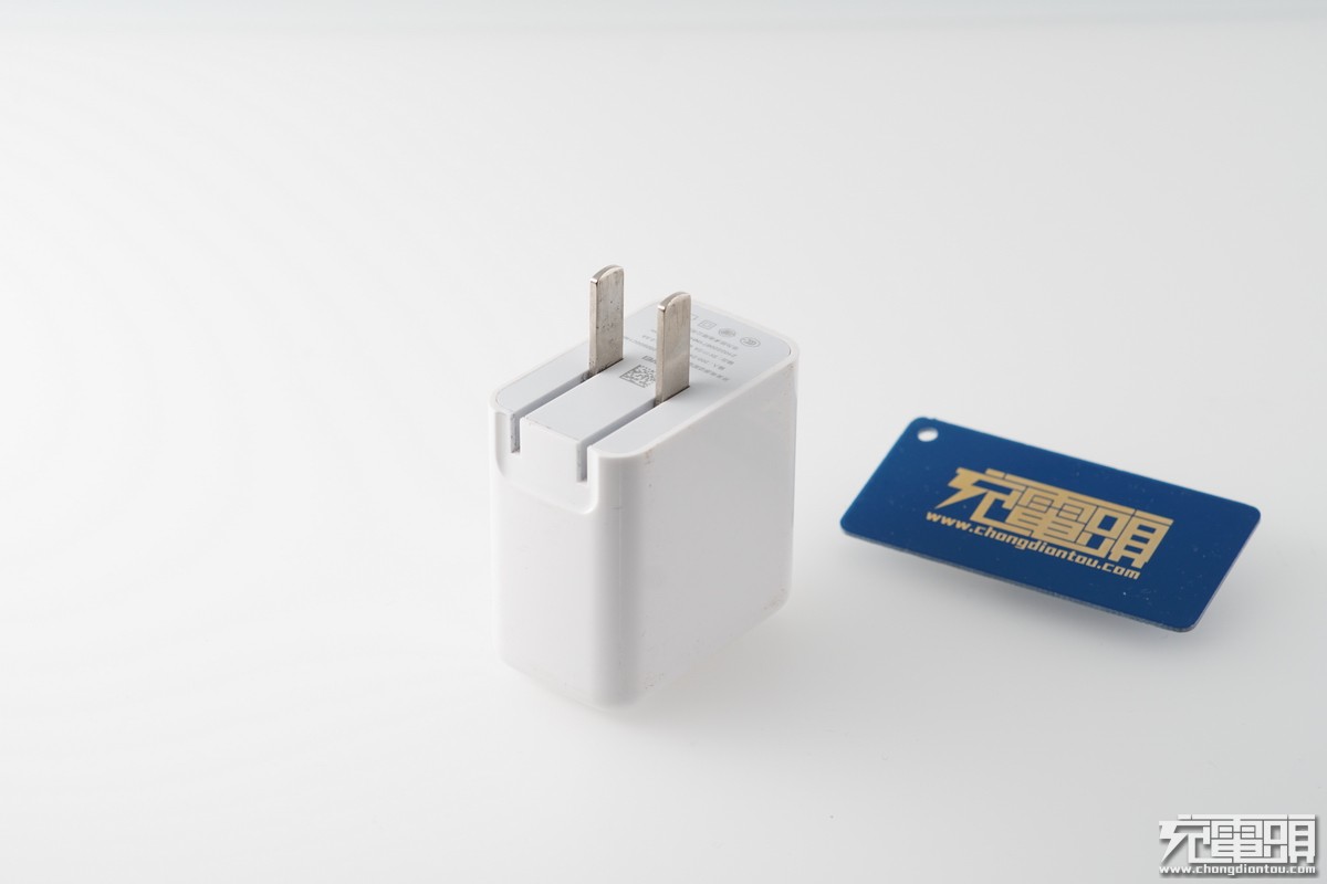
The charger can be folded, which is convenient for the user to carry.
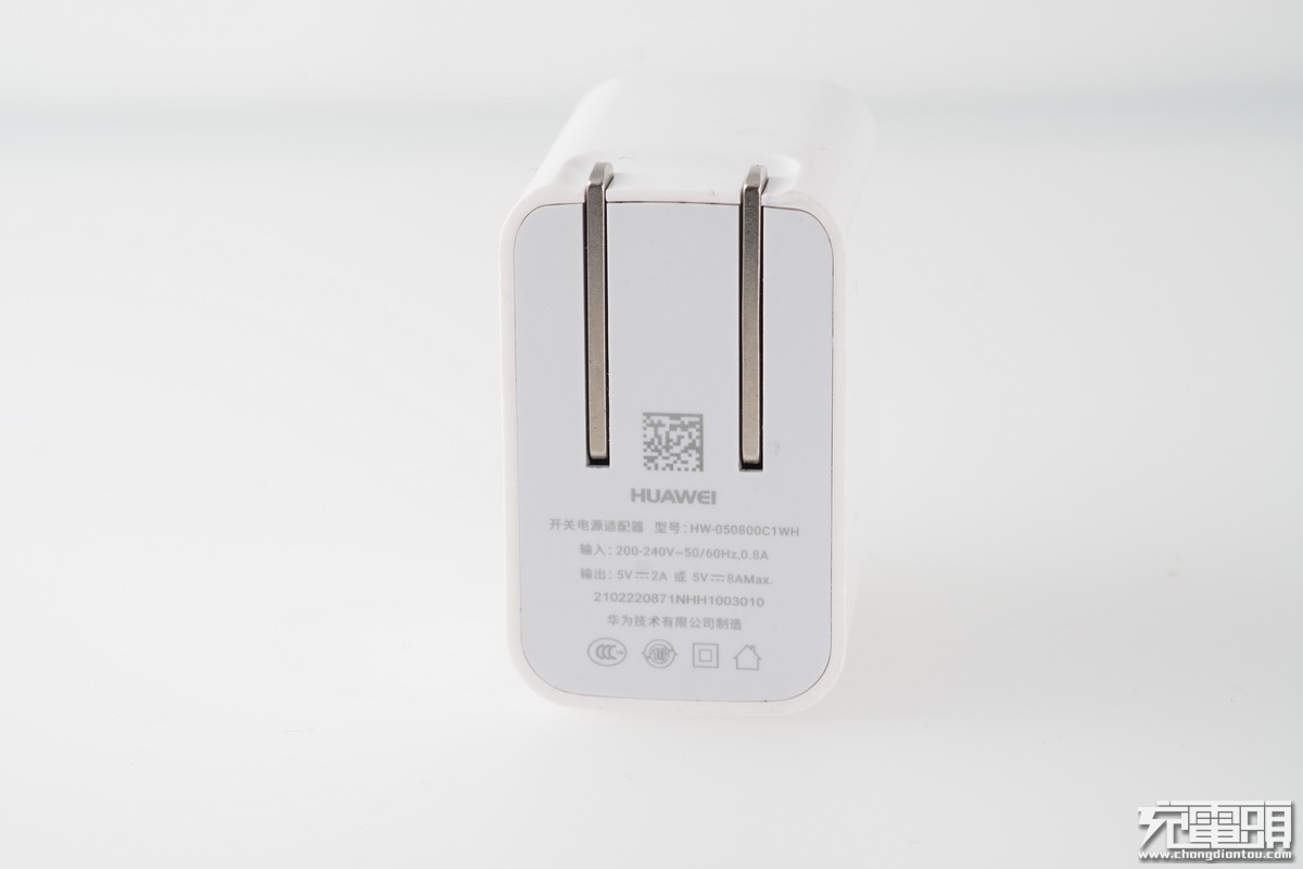
The charger specifications are as follows: Model number HW-050800C1WH, with an output voltage range of 200-240V. It provides two output specifications: 5V/2A and 5V/8A. This charger is manufactured by Huawei Technologies Co., Ltd. and has received 3C certification.
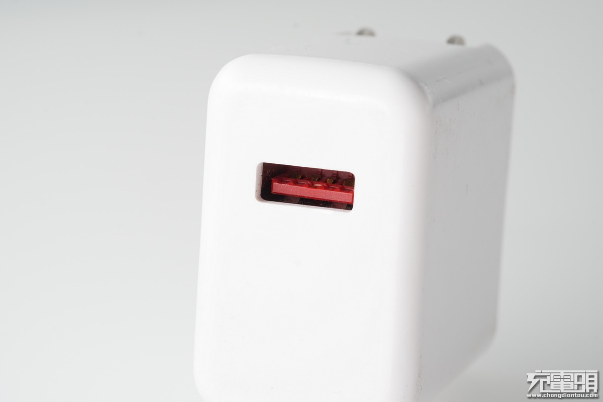
The charger provides an orange USB-A port with a widening contact spring.
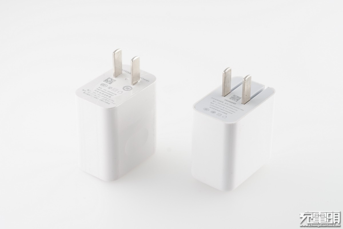
Another 22.5W Huawei charger uses SCP technology (left). The 40W charger that supports SCP technology is on the right.
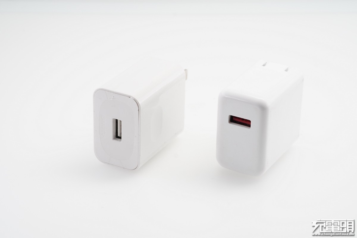
They have a different design on the USB port.

The 22.5W charger can not be folded, while the 40W charger can be folded.
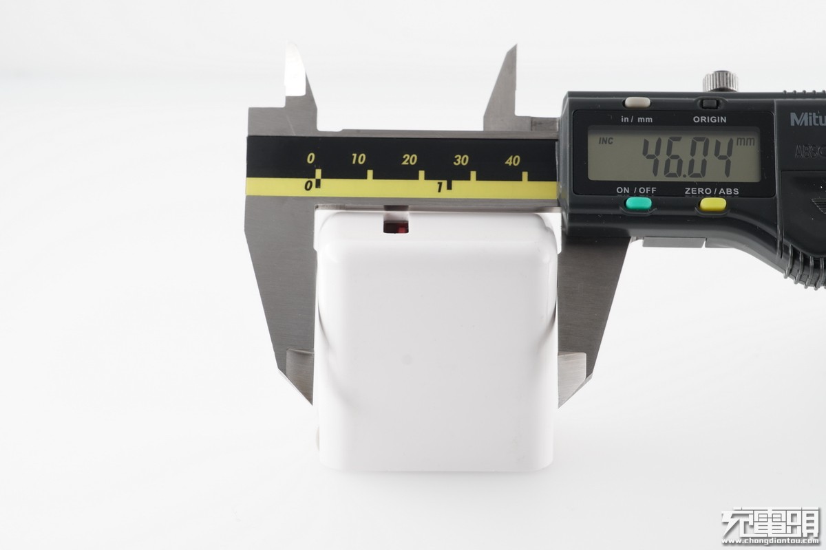
The charger is 46 mm wide.
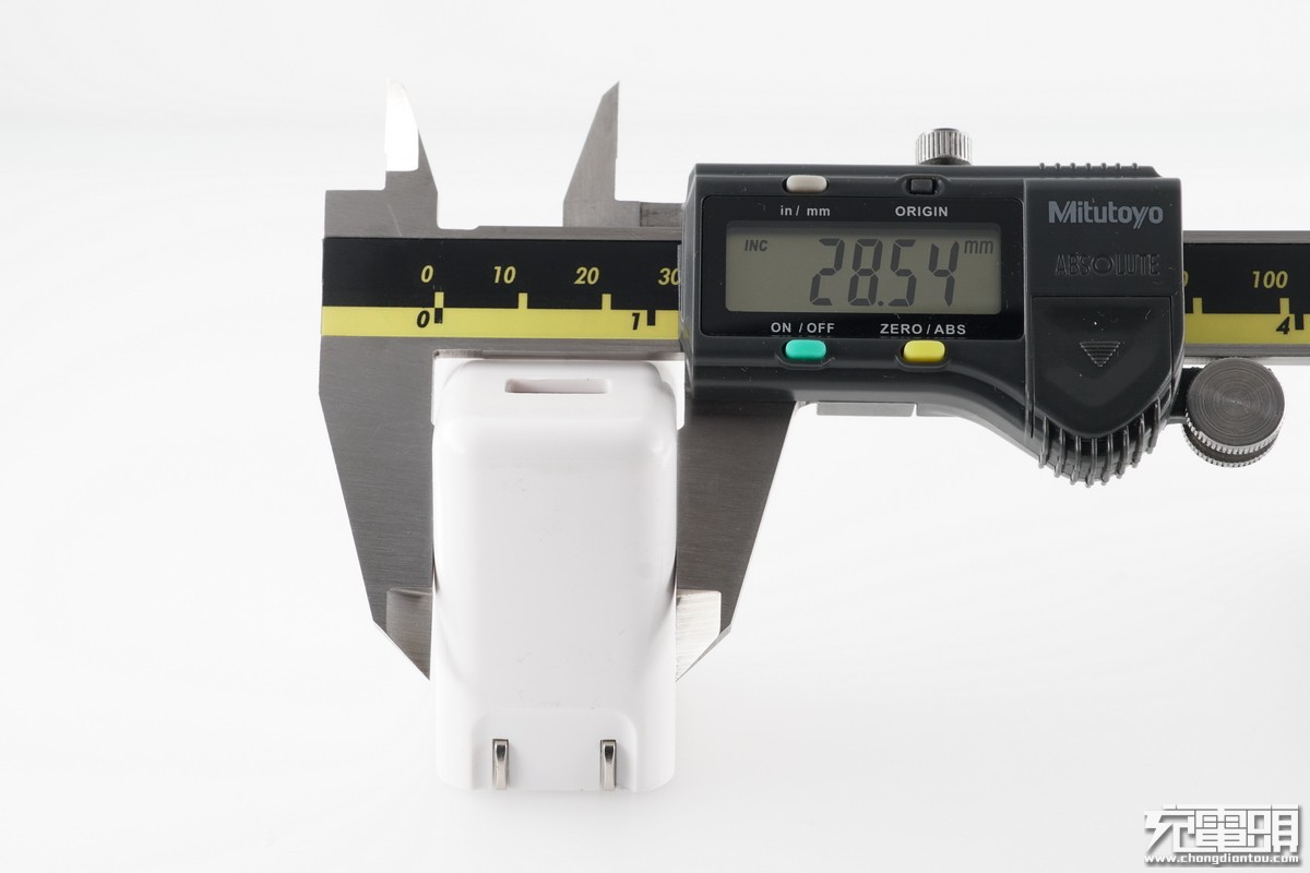
Its thickness is 28mm.
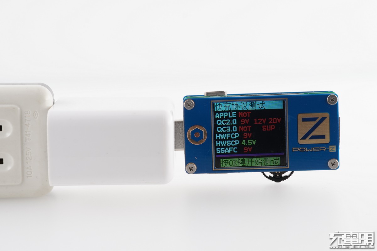
Using the ChargerLab power-z FL001 protocol to test the charger, we found that it only supports SCP.
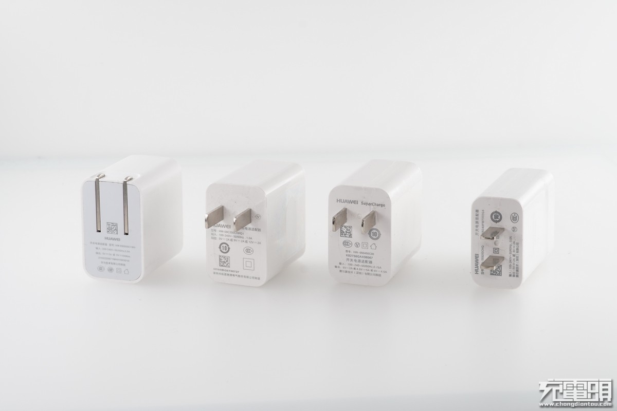
Huawei offers several quick chargers: the SCP 8A, PD, SCP 5A, and FCP+QC2.0 (from left to right).
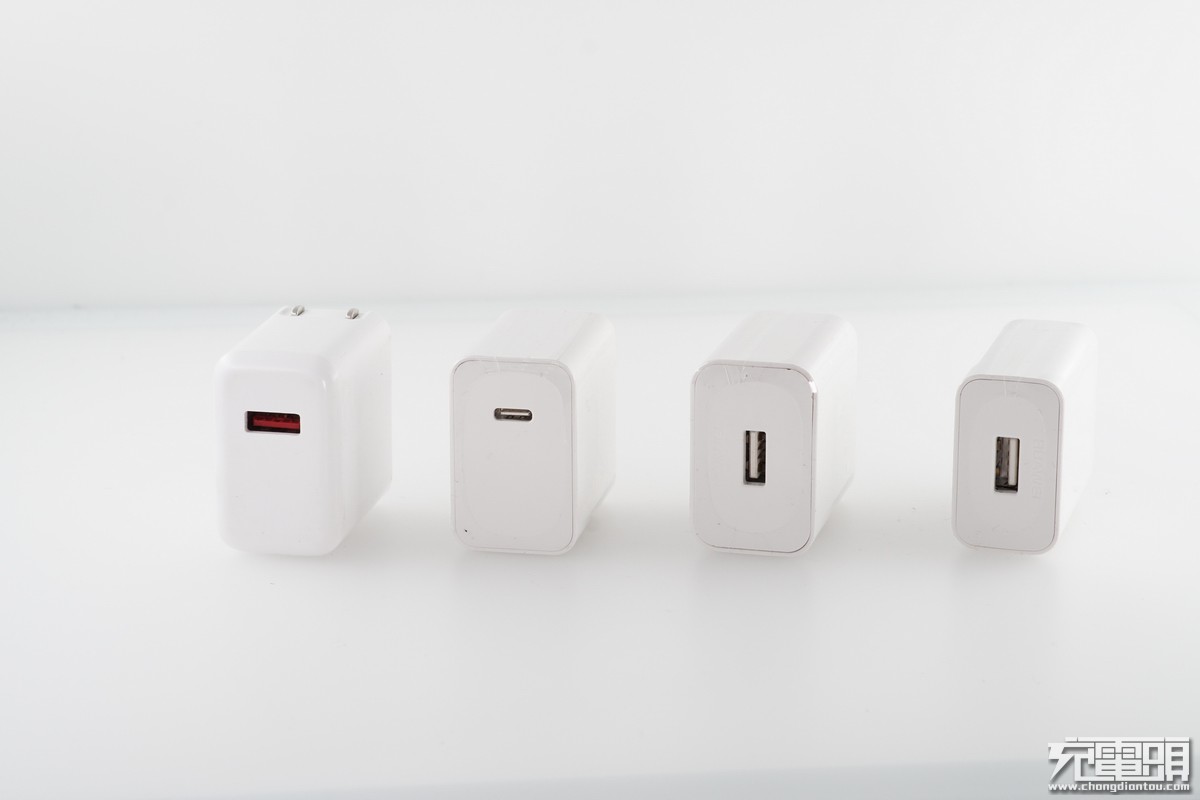
USB port comparison between four single-port quick chargers.
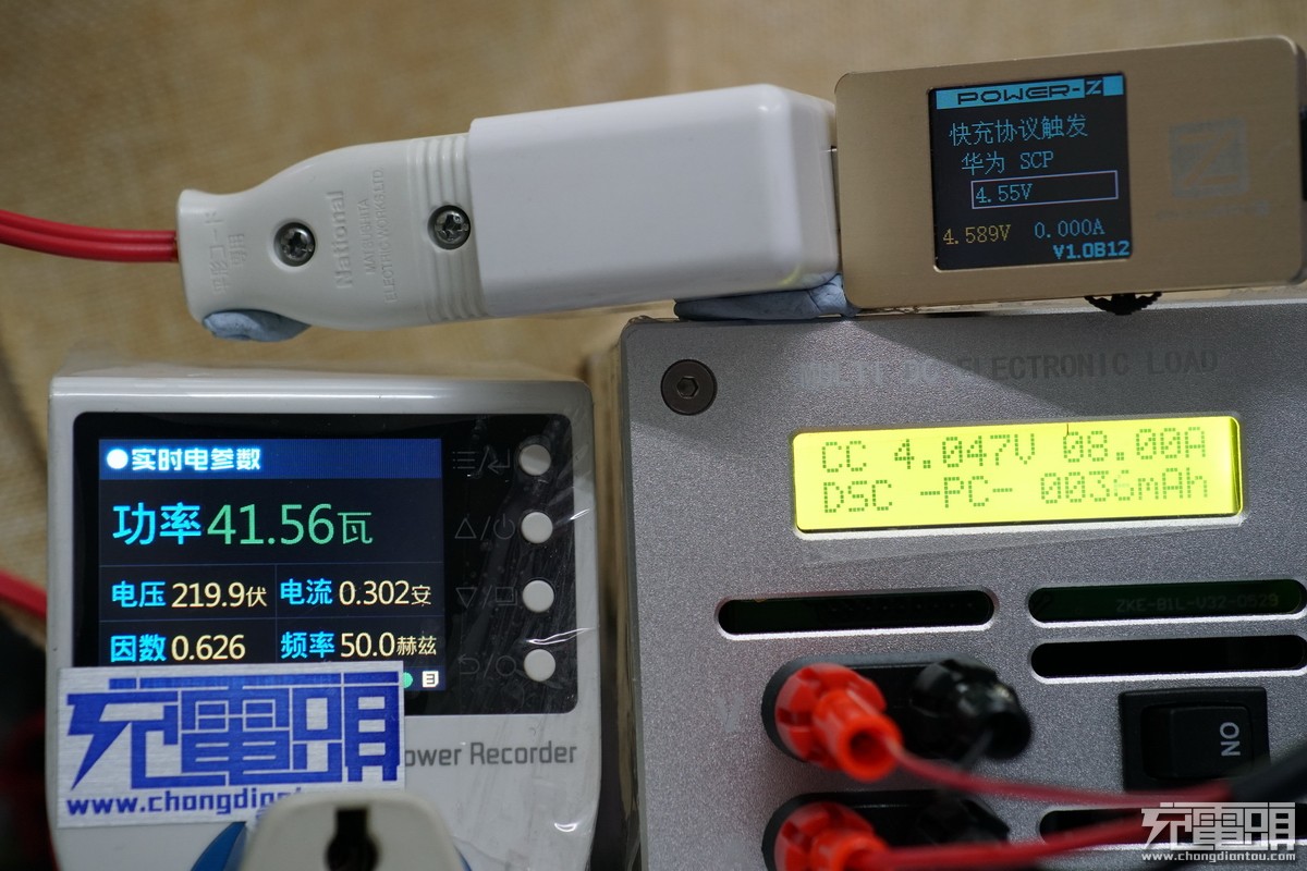
First, use the ChargerLab Power-2 FLD01 to test the charger. When the charger enters SCP mode, use EBC-A10 to test its maximum current, which is 8.2A.
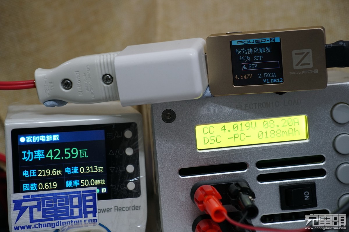
We conducted the test twice, and the result was 8.2A each time.
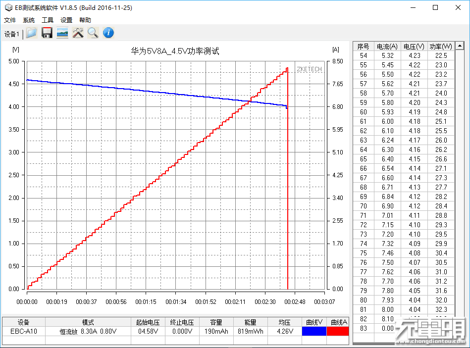
Huawei 40W charger power test. The maximum current recorded by the software is 8.1A.
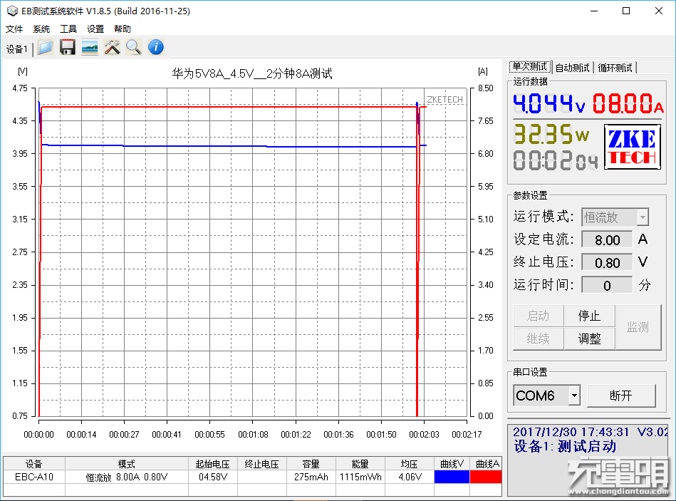
After testing the 40W charger fully loaded for two minutes, it still works well.
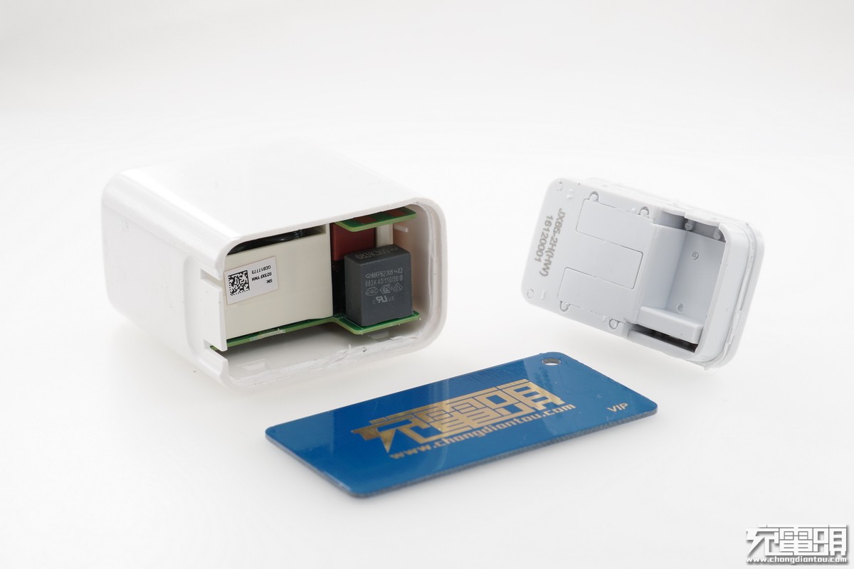
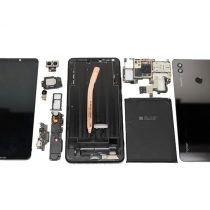
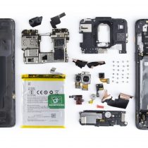
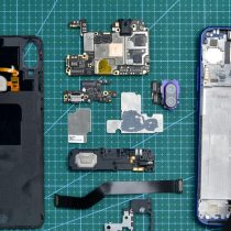
Remove the shell.
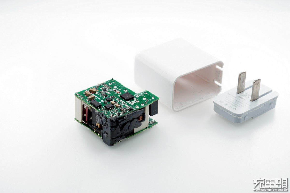
Pull out the PCB module.
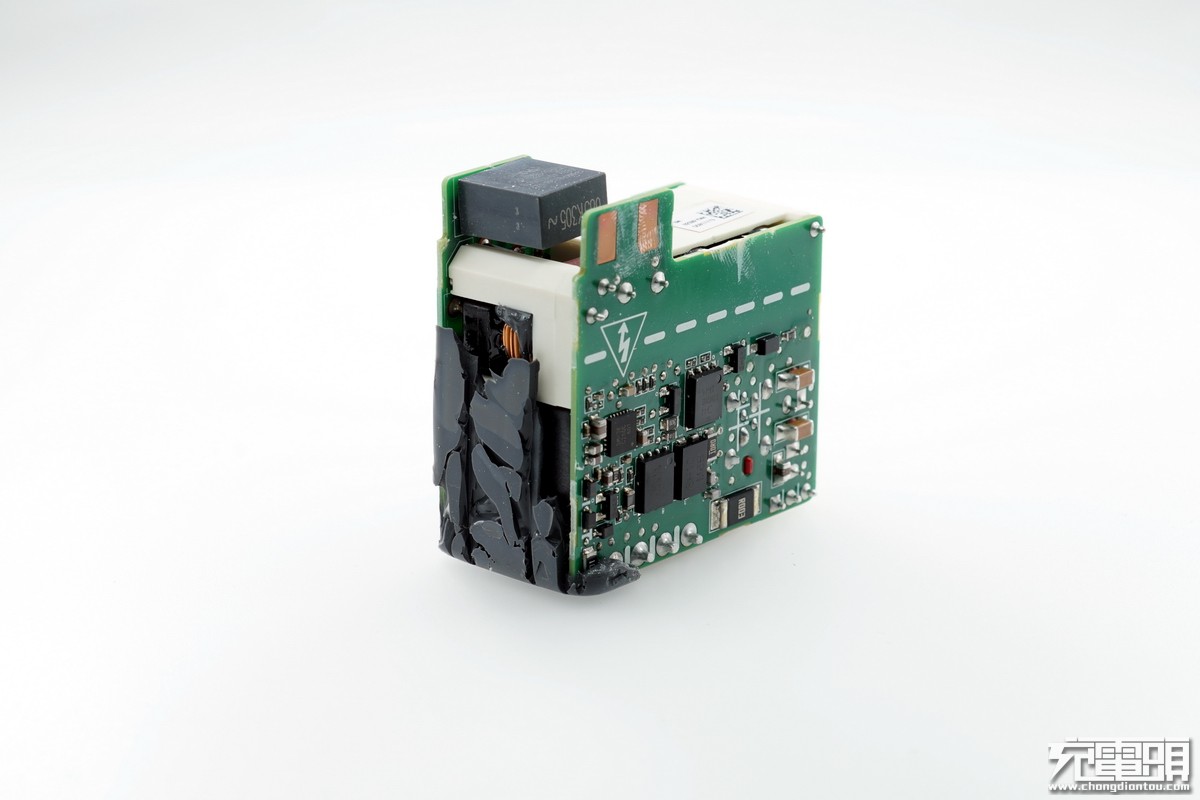
It consists of two PCB boards. The middle part uses an adhesive backing process, designed to secure the overall structure and enhance heat conduction.
There is also a plastic housing, which is used to secure the circuit board.
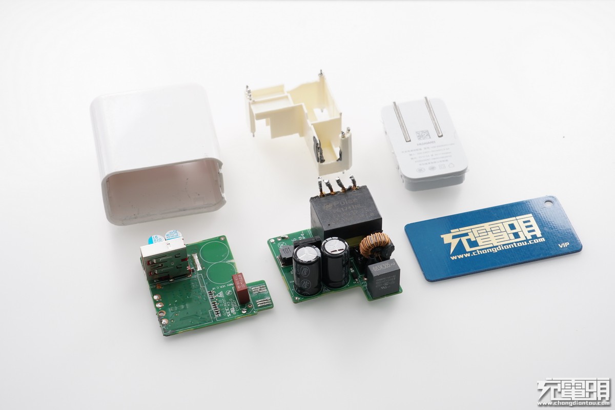
After removing two PCBs, we can see that the white plastic housing is used to connect the two circuit boards on the top and bottom.
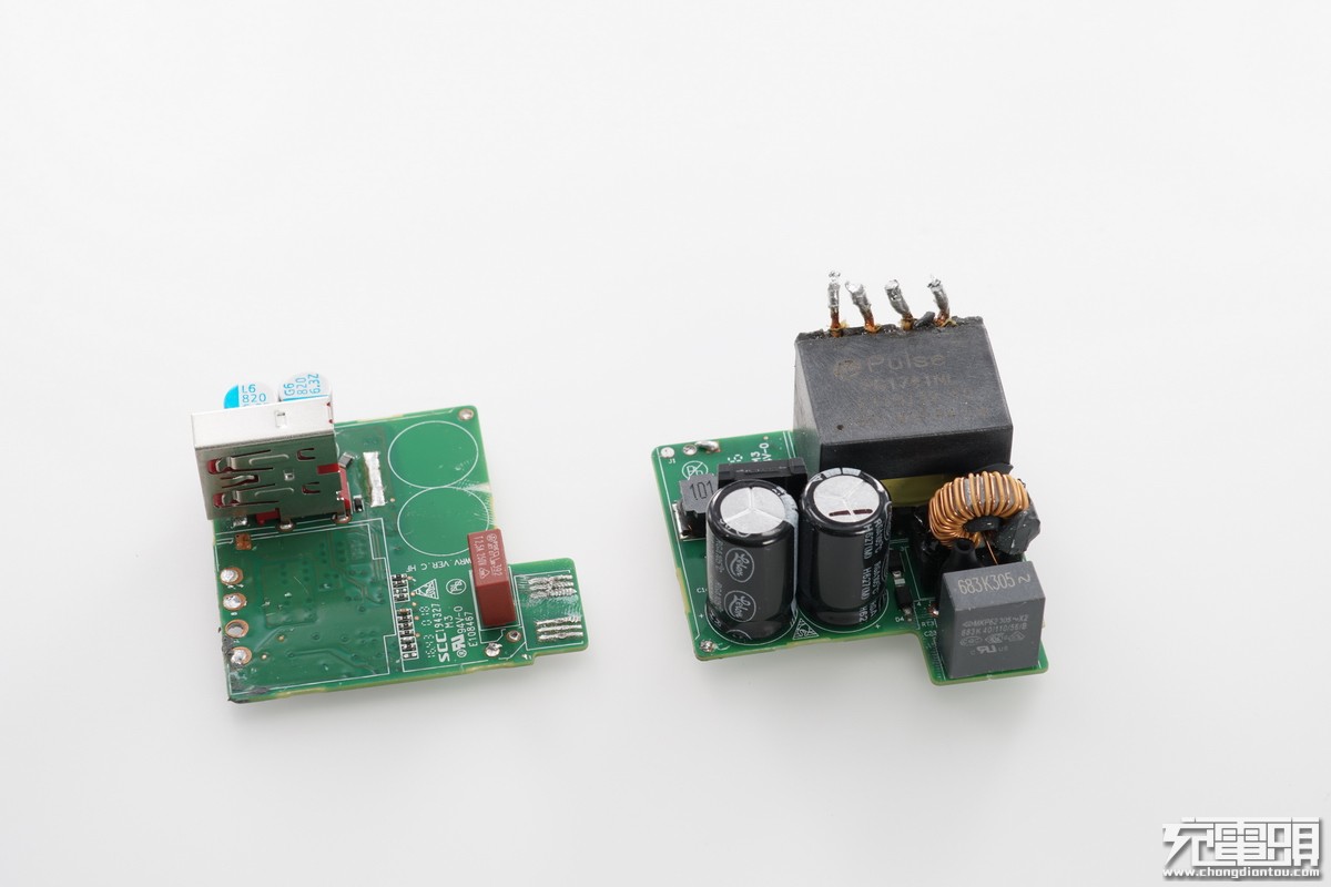
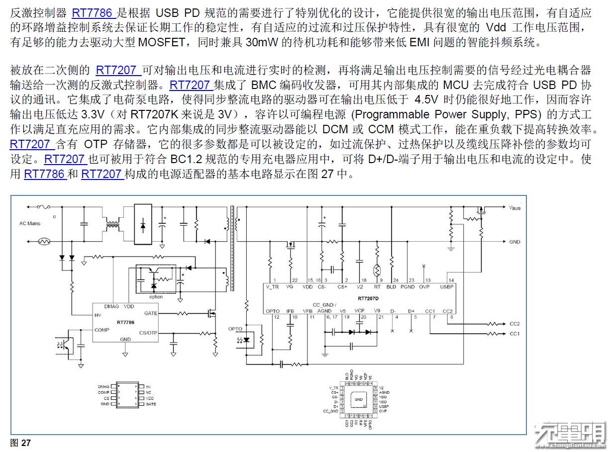
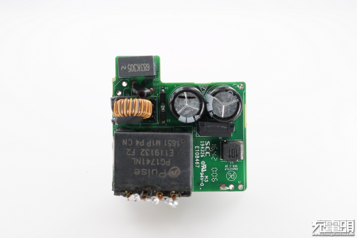
This is a transformer from PULSE. However, we haven’t found the model on the PULSE official website, so it is likely a customized version.
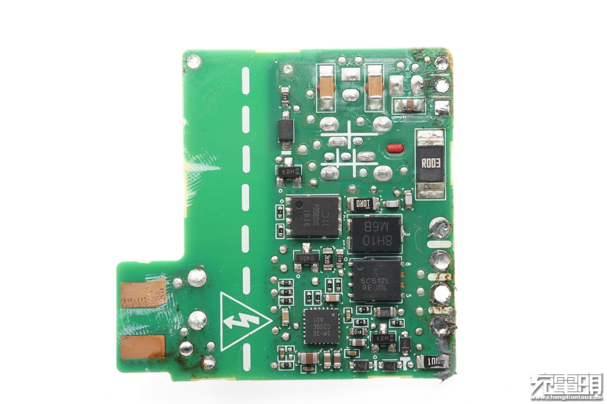
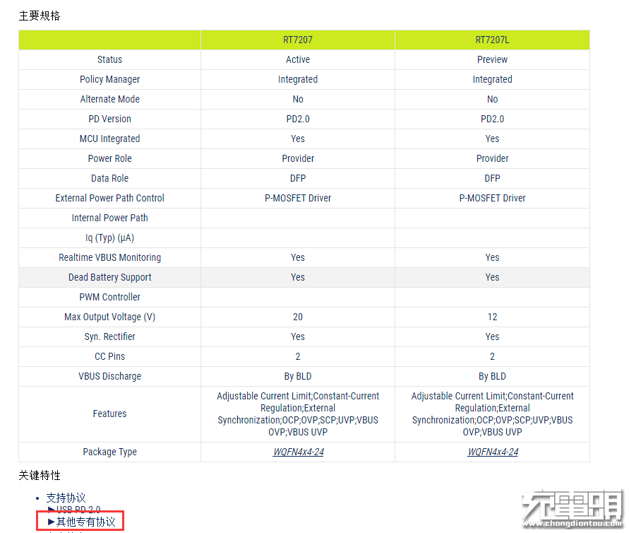
The circuit board on the left is RT7207, which supports synchronous rectification.
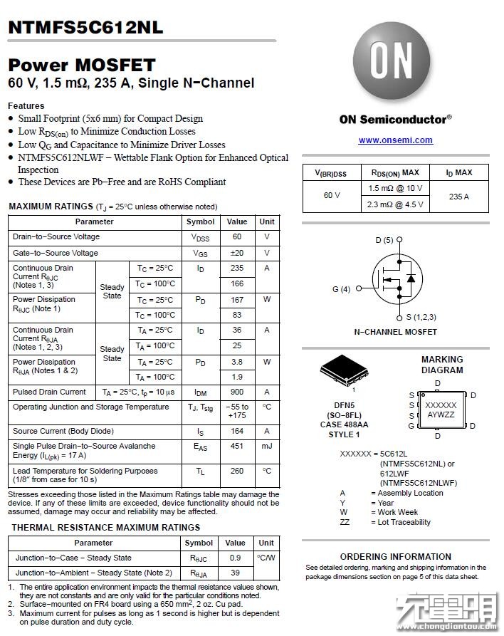
The synchronous rectifier has a parallel Schottky barrier diode to improve efficiency. It is an ON Semiconductor NTMFS5C6KNL, with the silkscreen marking 5C612L.
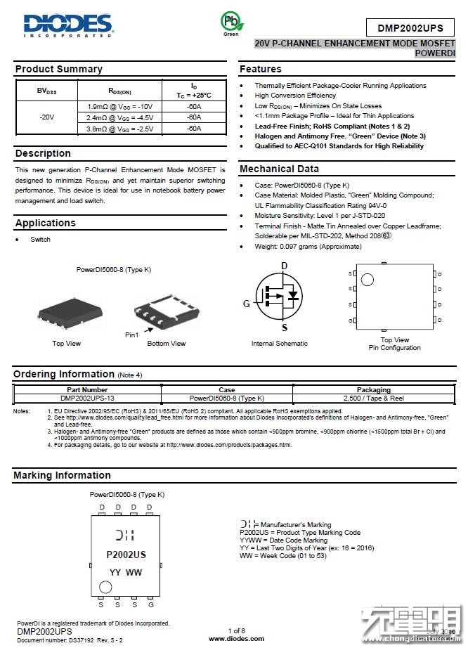
Output switch. Diodes PMOS DMP2002UPS.
The 2512 3 mΩ alloy resistor is used to detect the output current and close the output process if an abnormal current is detected.
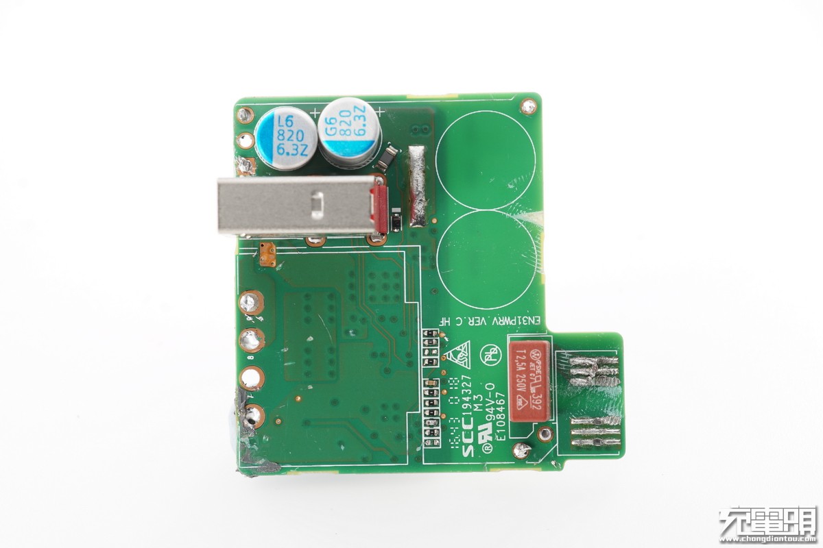
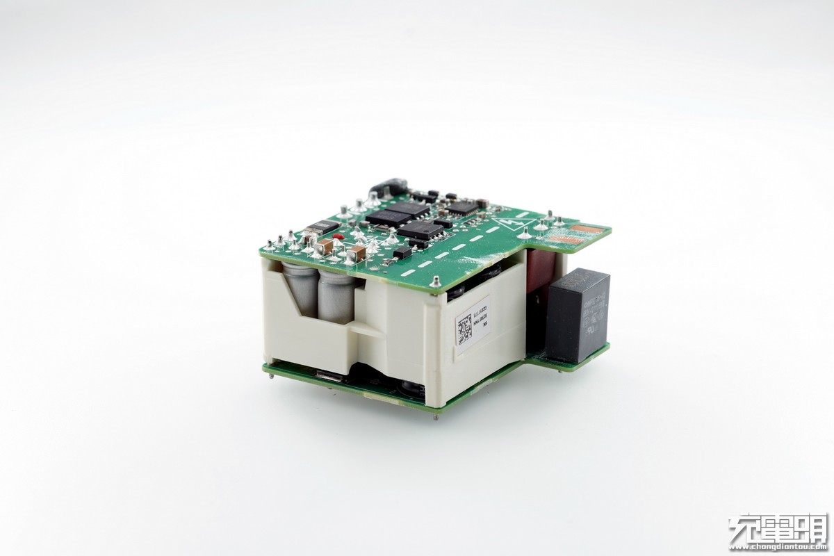
There are two solid capacitors on the front of the output board. The fuse for the AC input is located on this board.
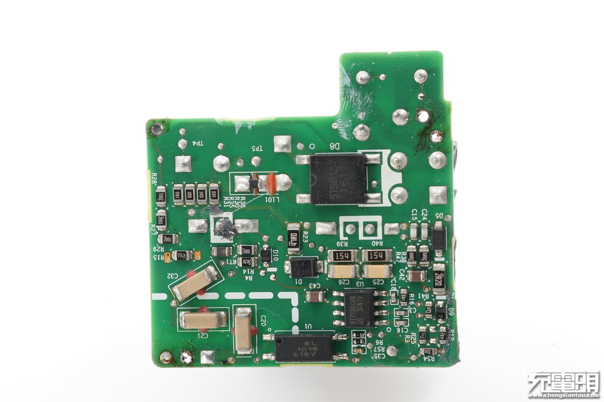
RT7786 is a primary PWM.
Three MLCCs connected in series are the traditional blue Y capacitor. These three series-connected MLCCs can improve insulation capability.
The input fuse is located on another circuit board. The thermistor is located between the X capacitor and the coil.
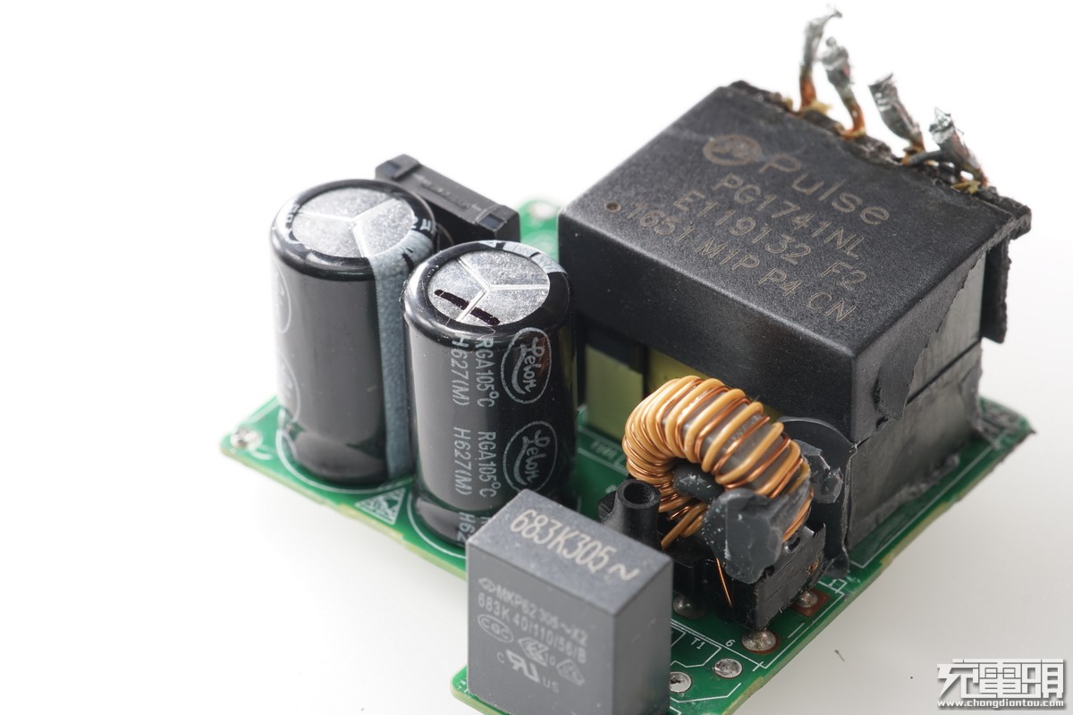
It uses Lelon capacitors.
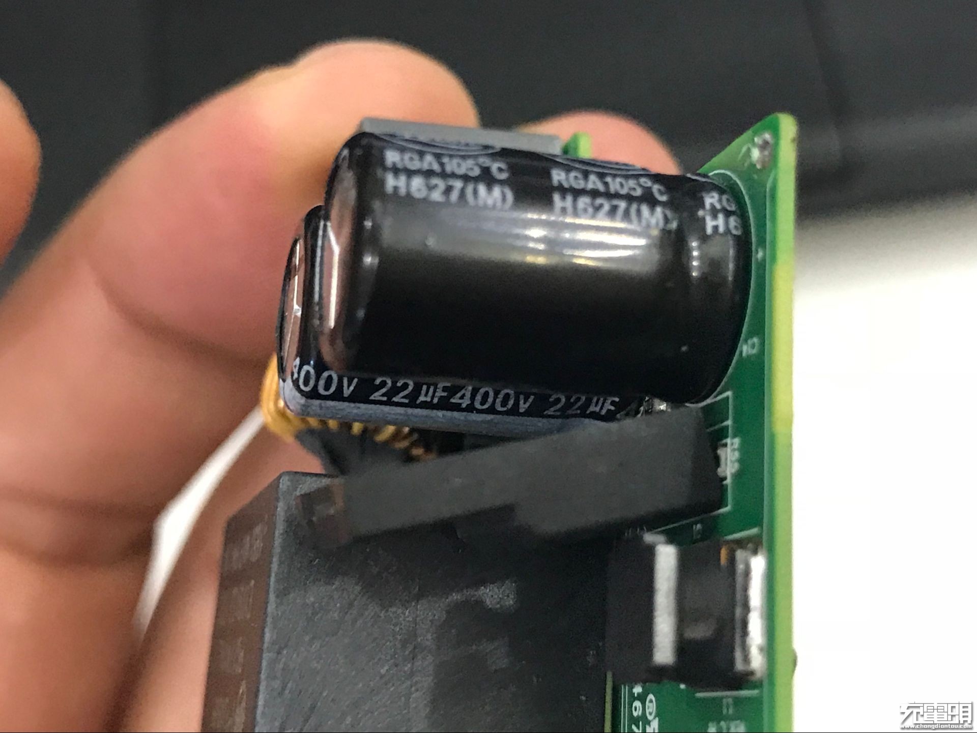
400V/22μF
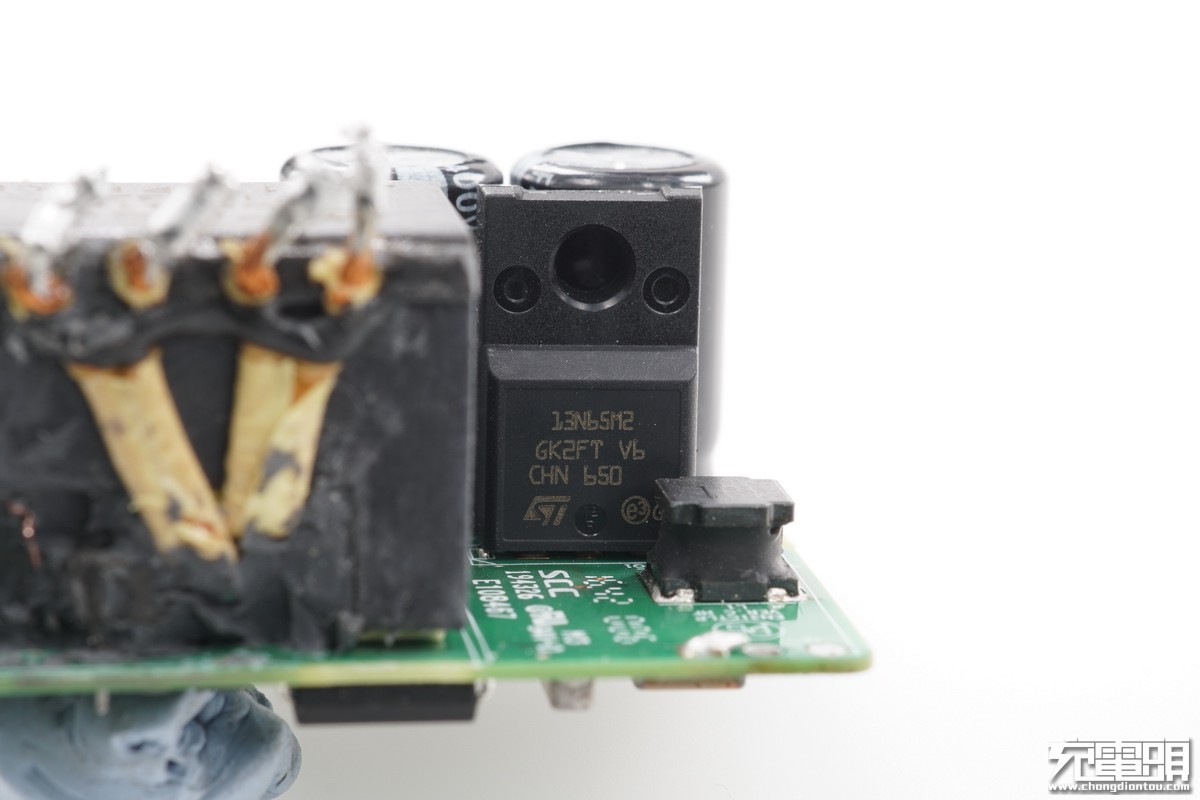
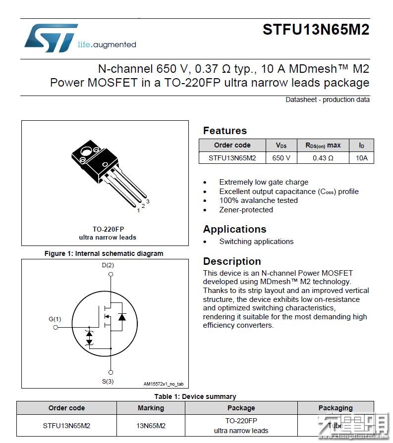
It is switch tube STFU13N65M2.