In this guide, we will show you how to remove and replace the display assembly on the Huawei Mate 9 smartphone.
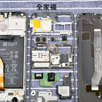
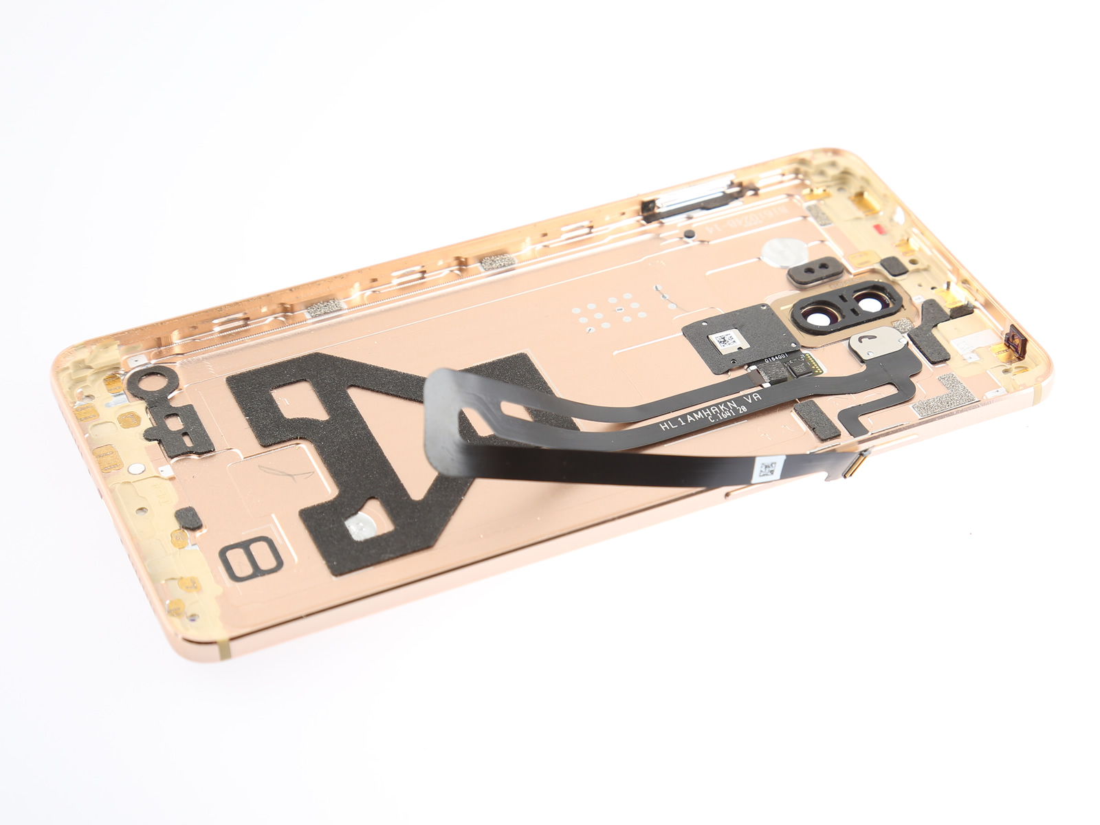
To remove the display assembly, you need to remove the SIM card tray, back cover, rear camera, front camera, motherboard, USB board, and loudspeaker.
Teardown is what we do! Follow us on Facebook for the latest repair news.
Repair Tools Needed:
T2 Torx Screwdriver
Phillips #000 Screwdriver
Suction cup
Pick
Tweezers
Spudger
SIM Card Eject Tool
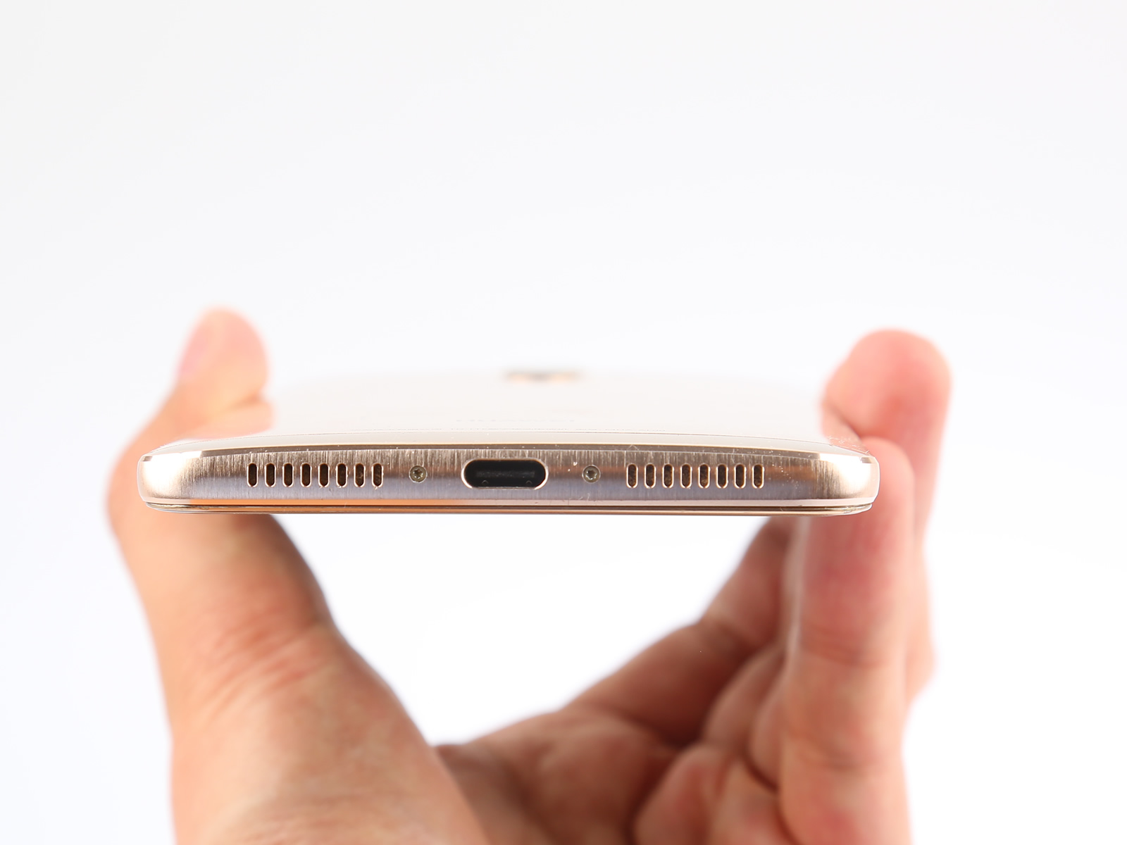
1. Remove the SIM card tray and two T2 screws
First, turn off your Huawei Mate 9 and remove the SIM card tray using a SIM card eject tool.
Remove the two T2 screws located at the bottom next to the USB Type-C port.
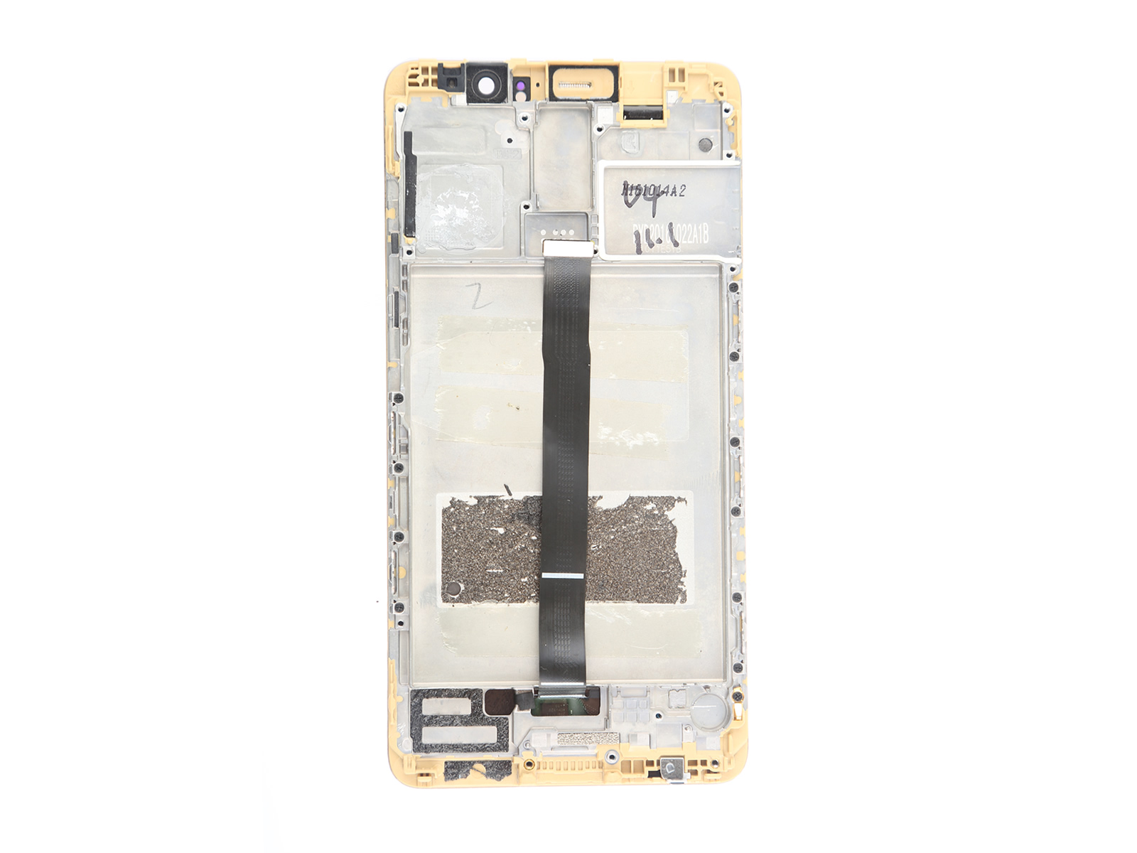
2. Separate the back cover
Use a suction cup to separate the display assembly from the back cover.
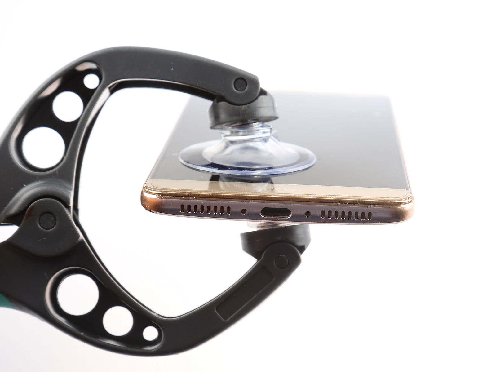
Lift the display a little bit with a suction cup and insert a pick.
Slide the pick along the display edge on both sides.
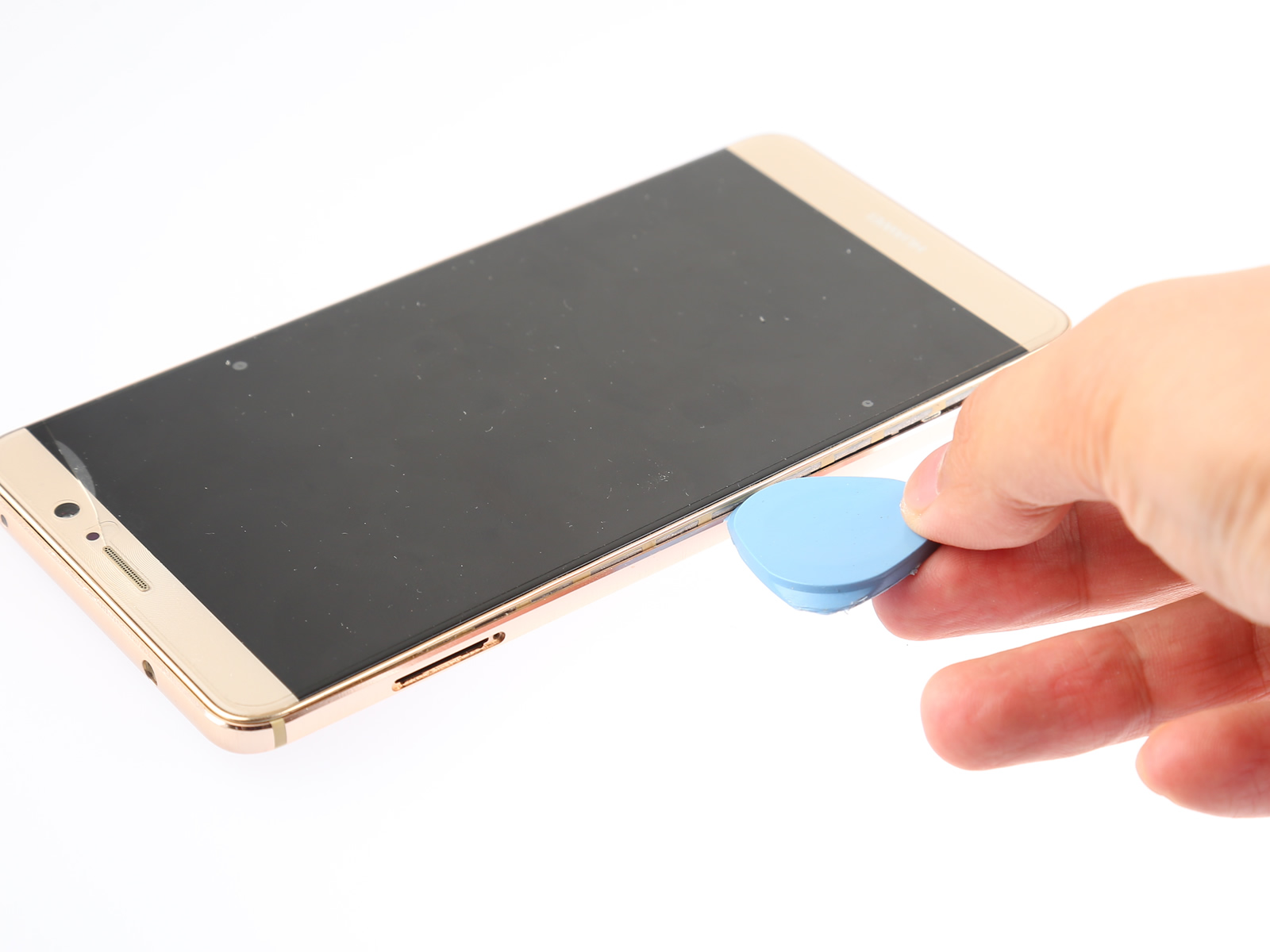
Please don’t remove the back cover completely. The fingerprint and power button cable is still connected to the motherboard.
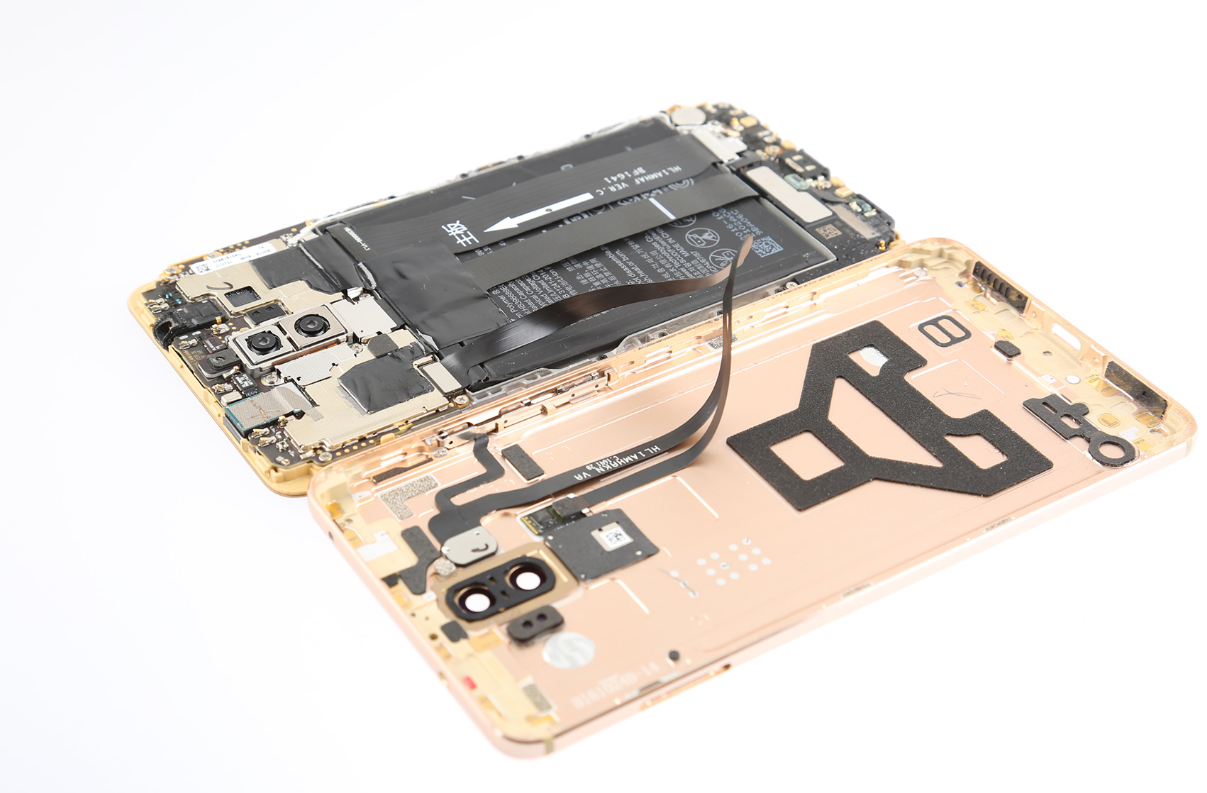
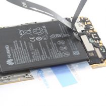
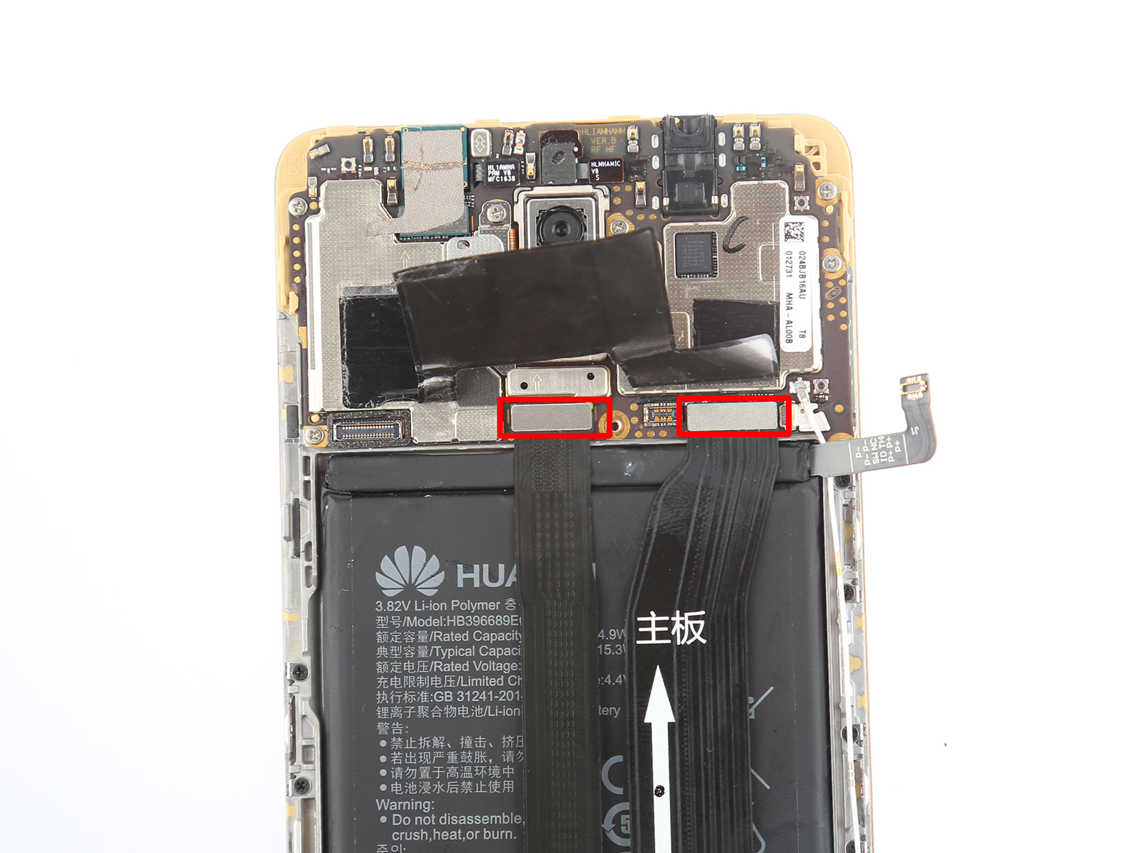
3. Disconnect the battery connector
To protect the internal components, we need to disconnect the battery connector.
Remove the screw securing the metal plate.
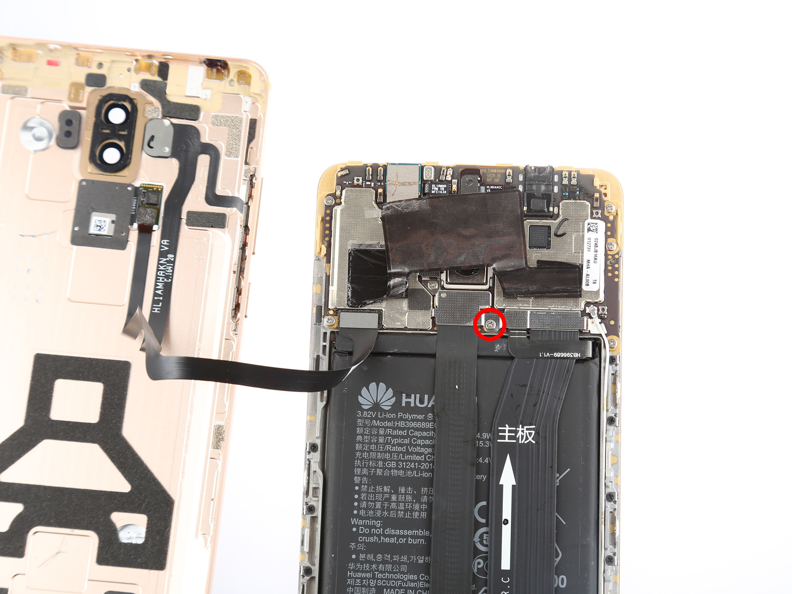
Remove the metal plate using tweezers.
Disconnect the battery connector from the motherboard.
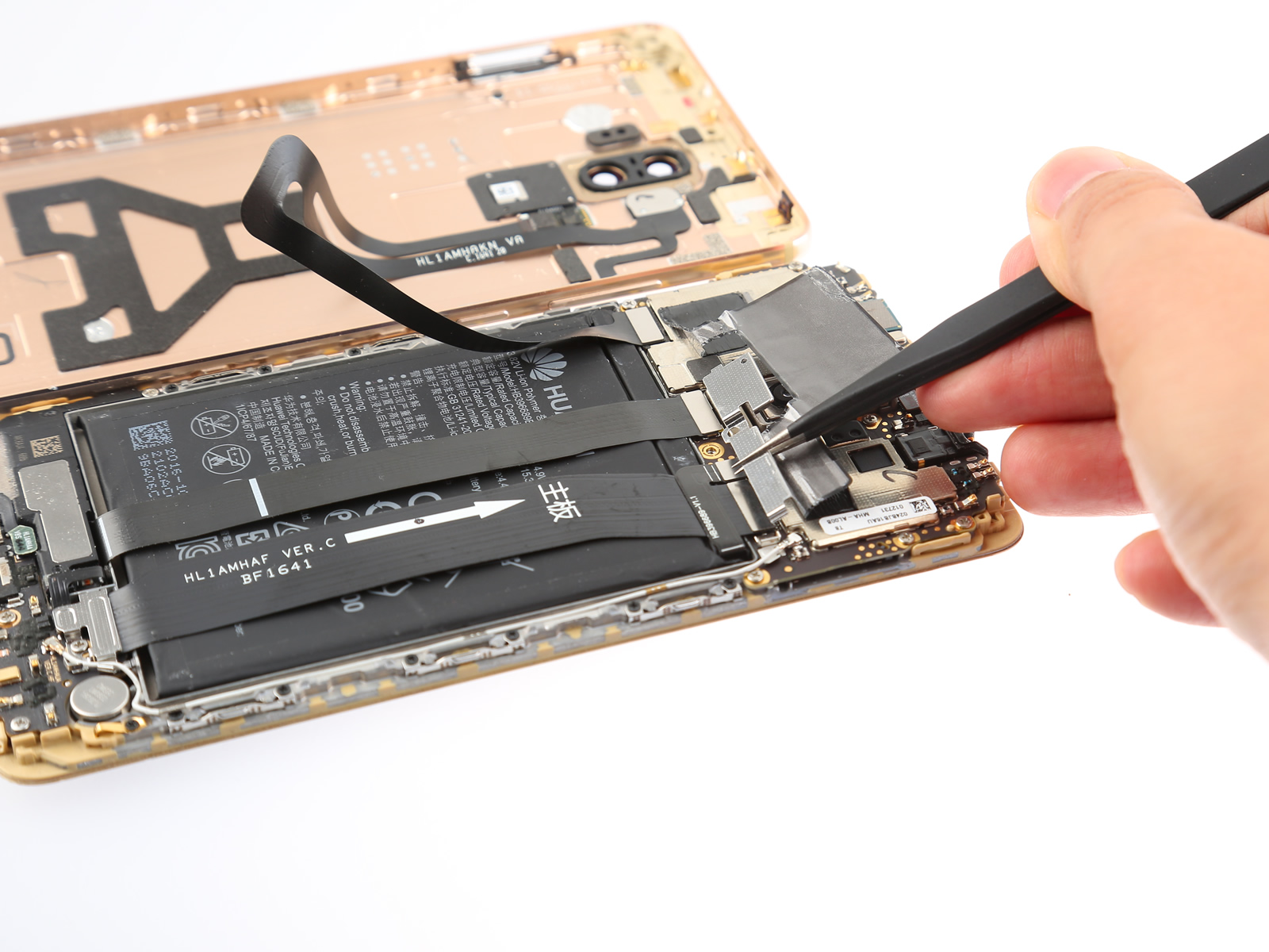
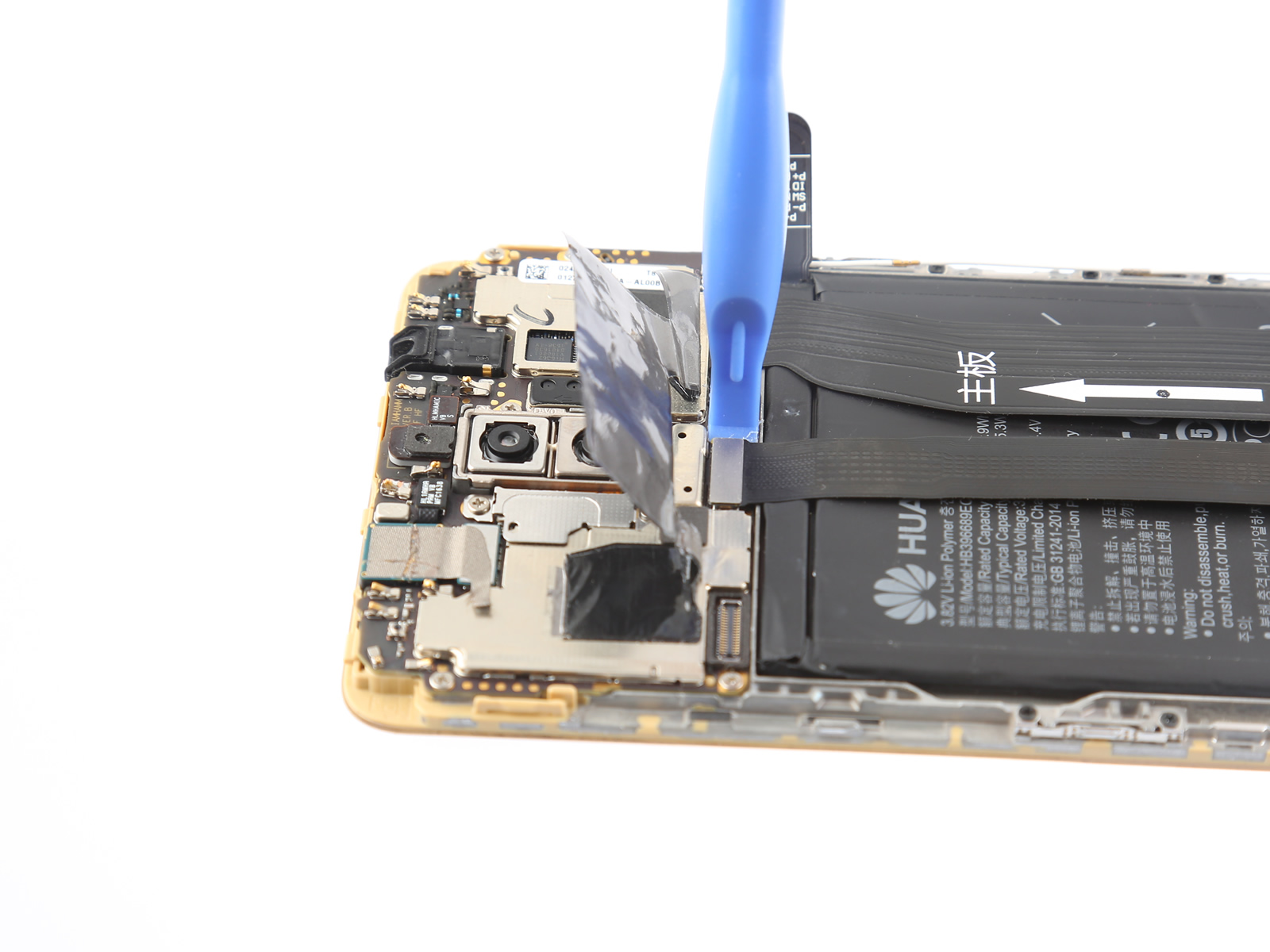
4. Remove the back cover
Disconnect the battery connector with a spudger.
Now, you can remove the back cover completely.
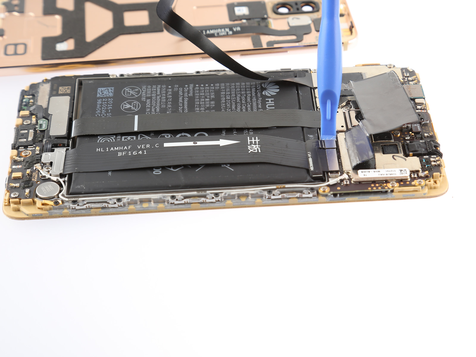
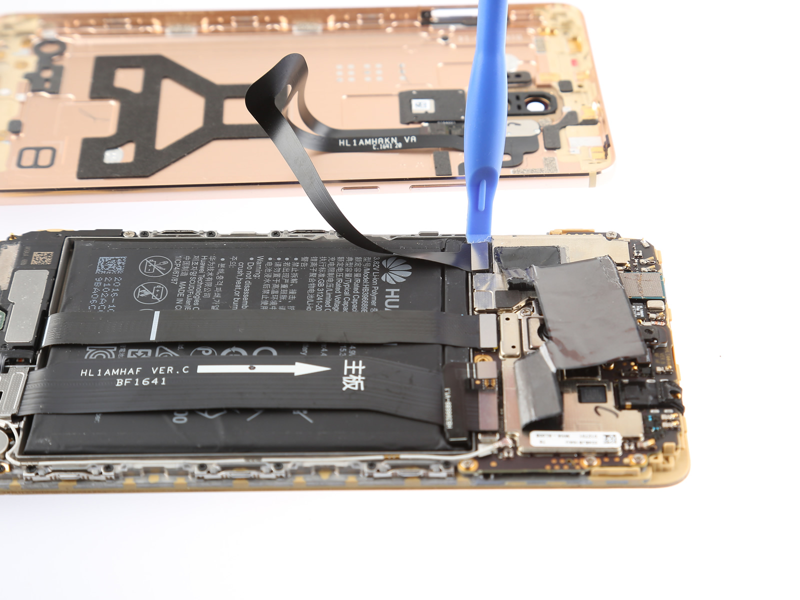
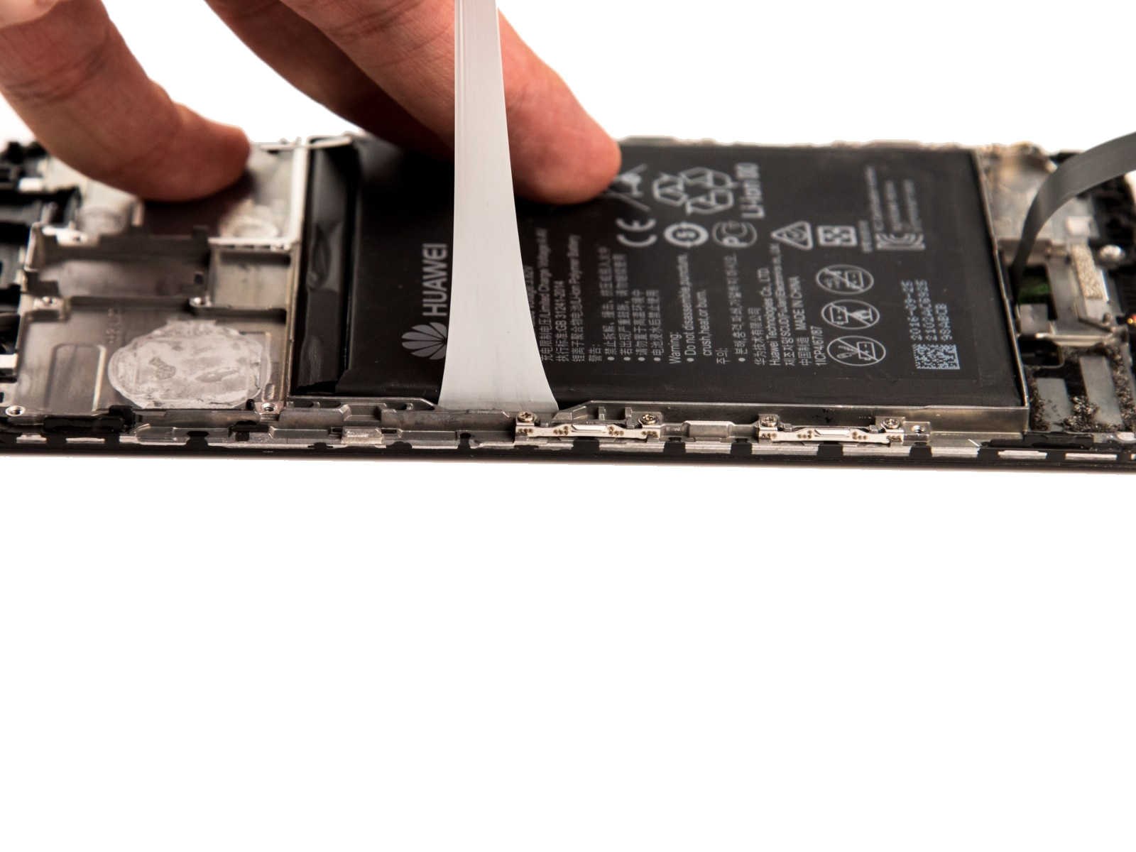
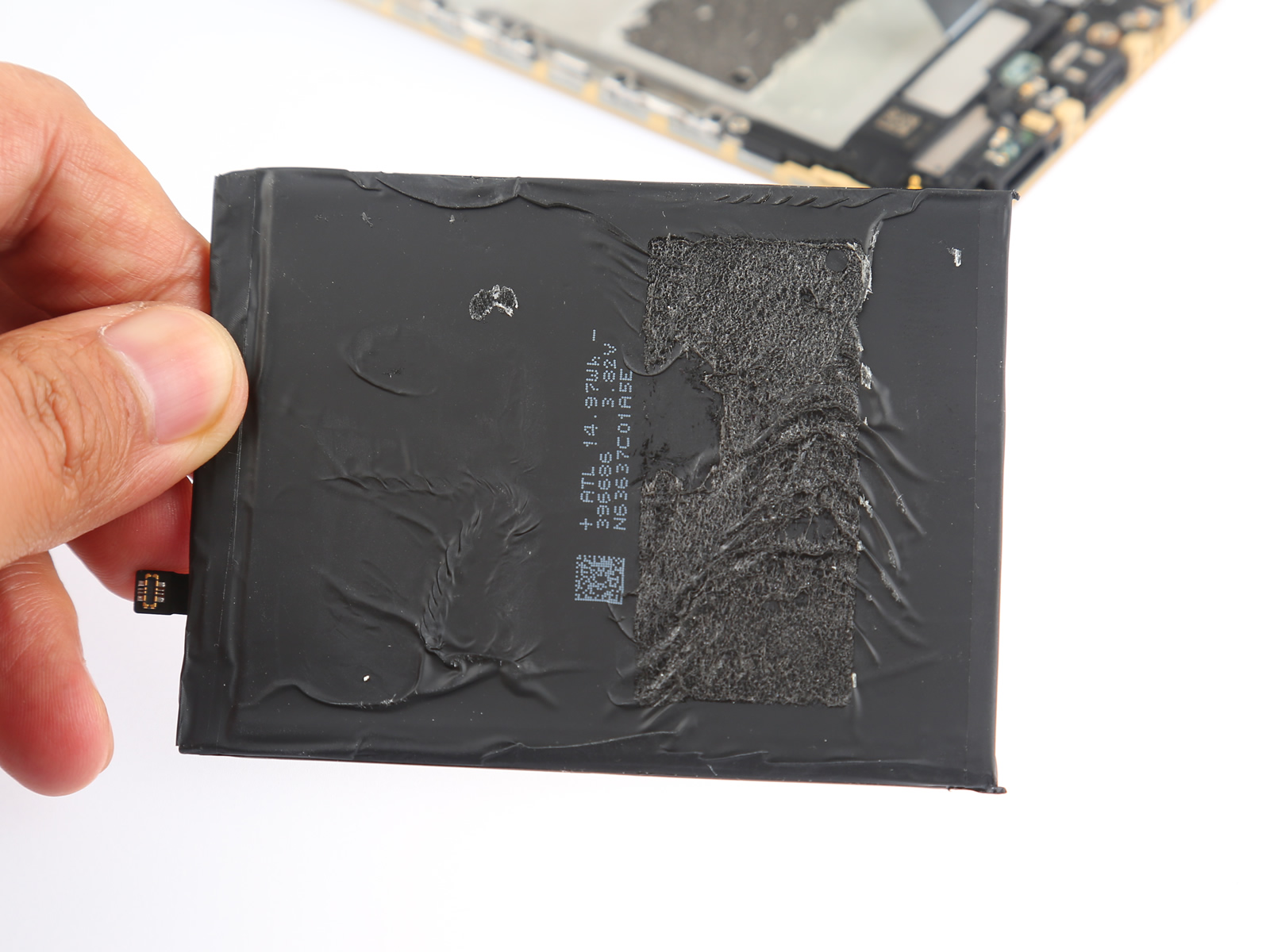
5. Remove the battery
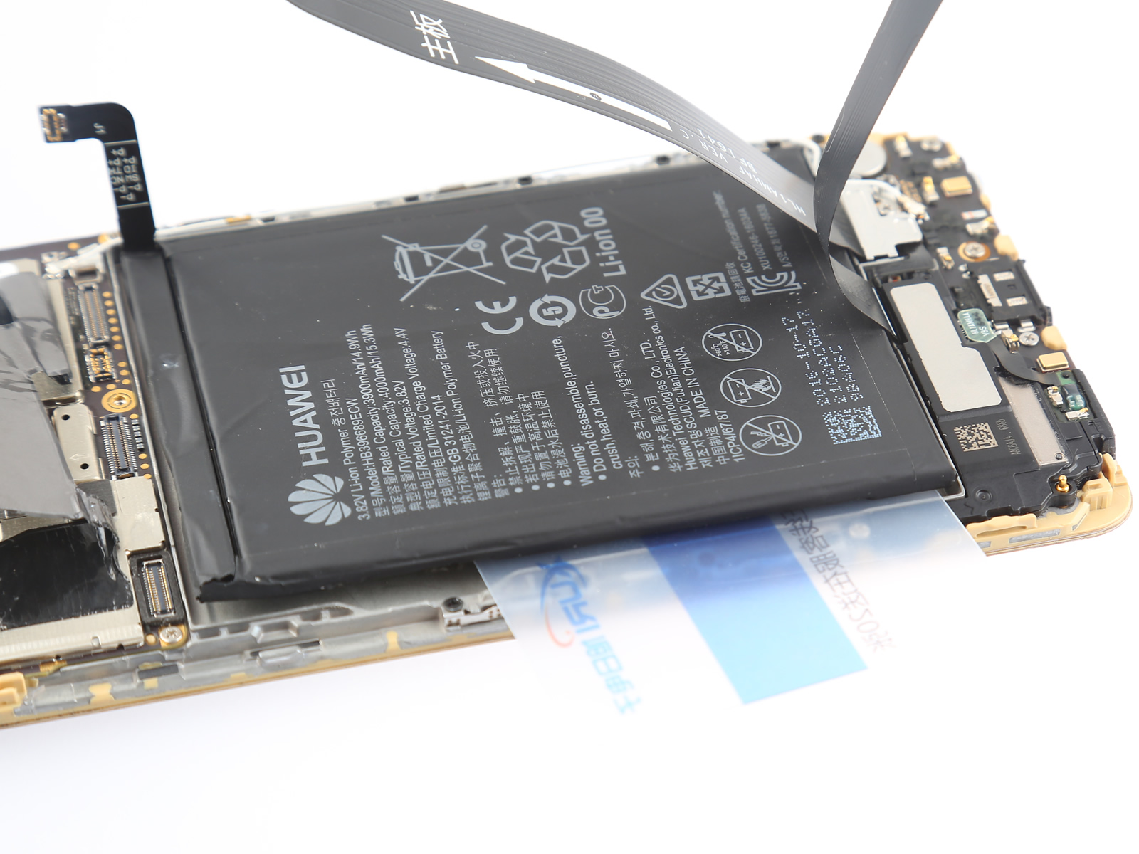
Disconnect the display cable and main FPC from the motherboard.
Uncover the ends of the adhesive pull tabs to get a good grip on them.
Pull the tab slowly and continuously to release the battery.
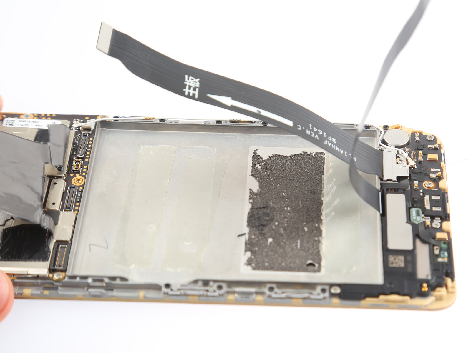
Insert a card under the battery to separate the battery.
Because the battery is very thin and easy to bend, I highly recommend prying it out with the old card.
As you can see, there is a layer of foam adhesive used to hold the battery in place.
6. Remove the motherboard
Remove the eight screws with a Phillips #000 Screwdriver.
Disconnect the light distance sensor connector.
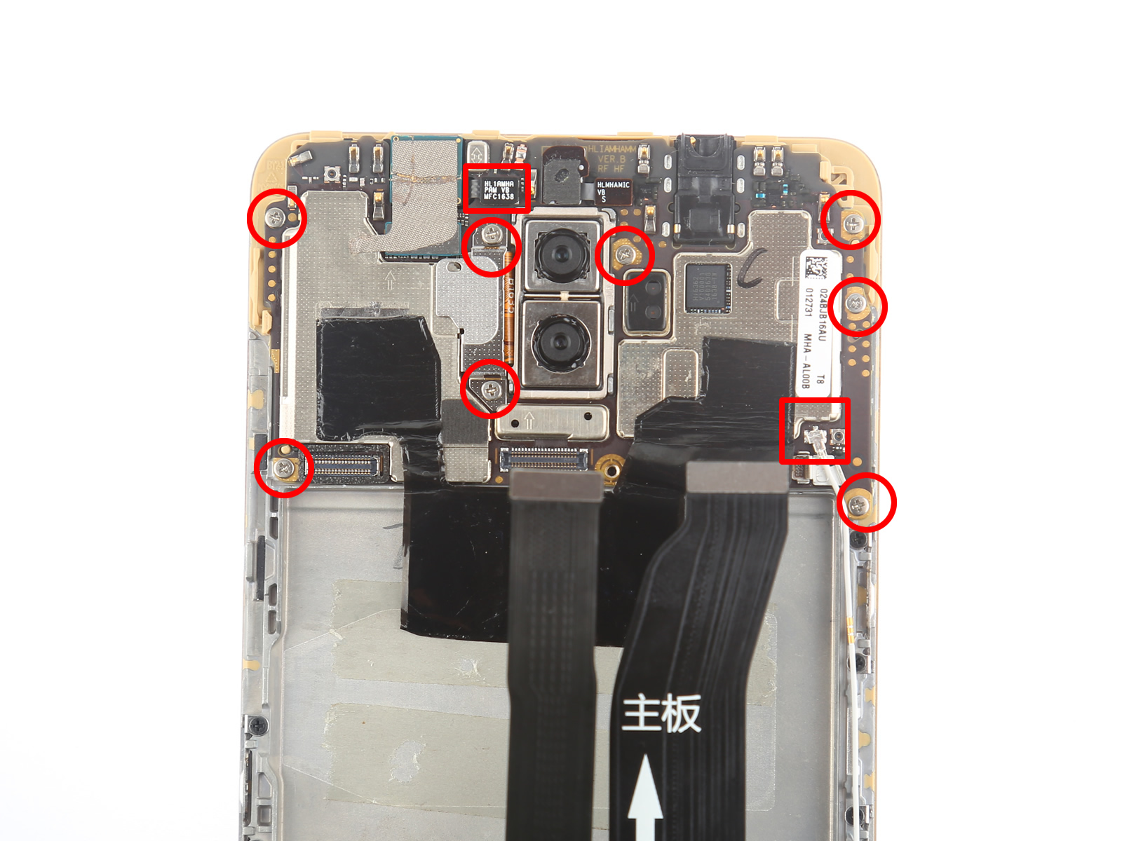
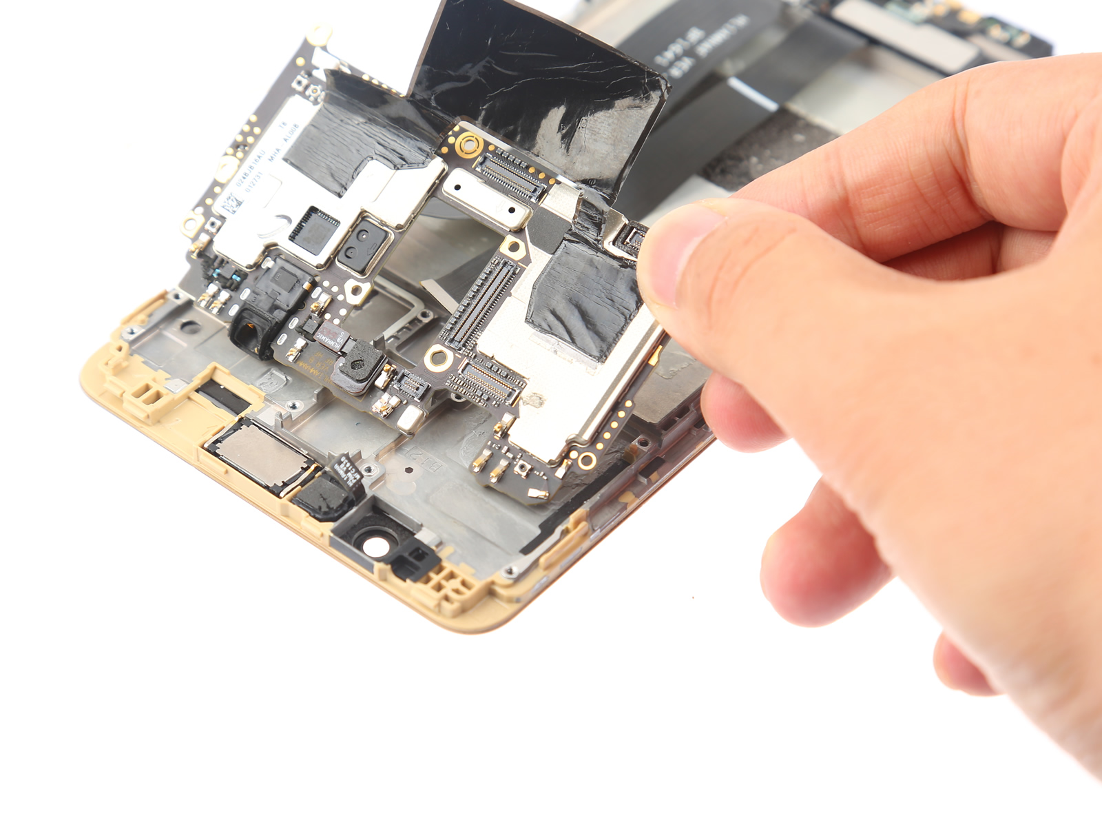
Peel off the conducting fabric.
Unplug the camera connector from the motherboard. Now you can remove the front camera.
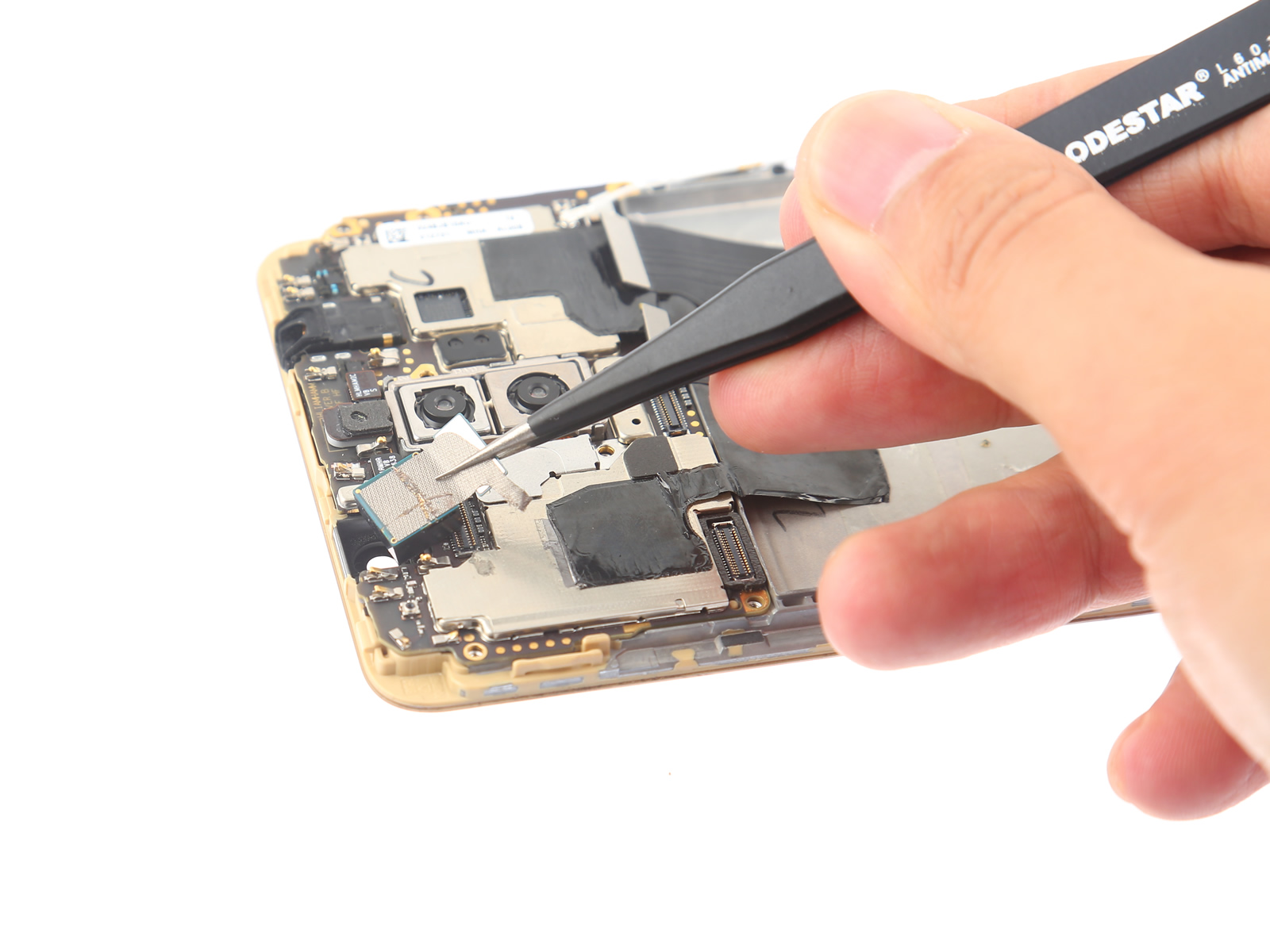
Remove the metal plate that covers the rear camera connector.
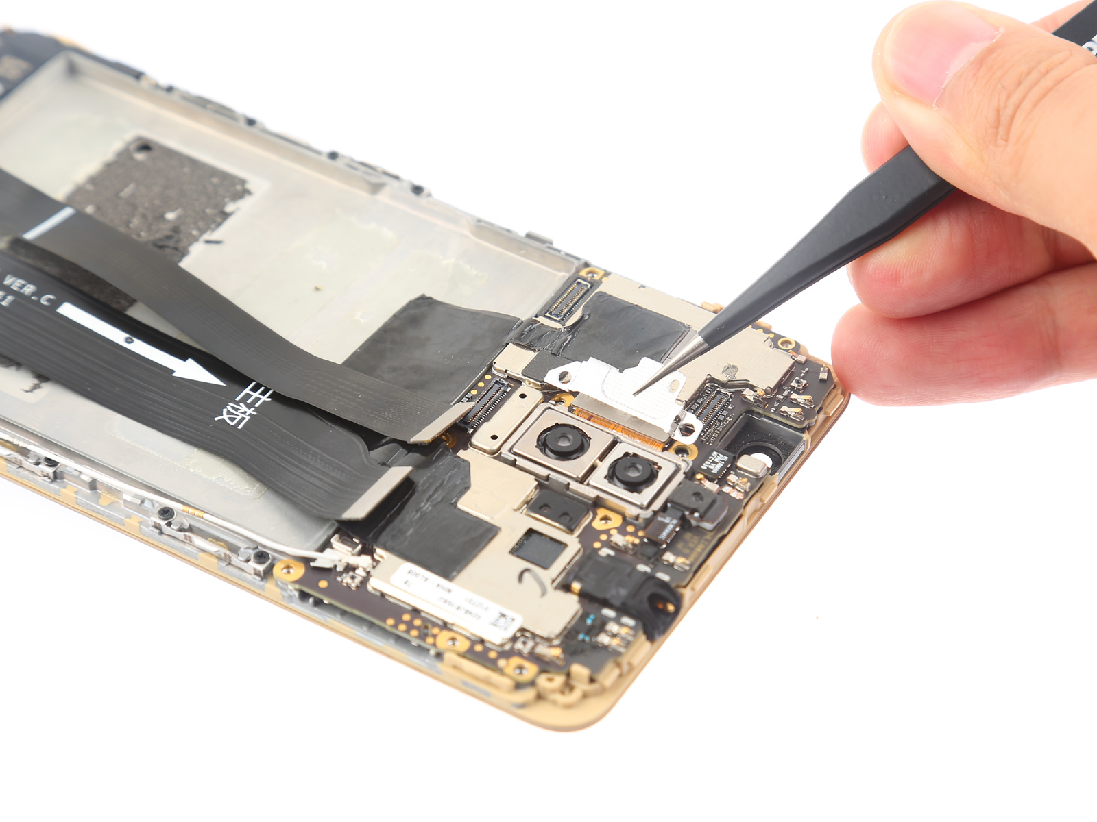
Disconnect the rear camera connector and take out the rear camera from its slot.
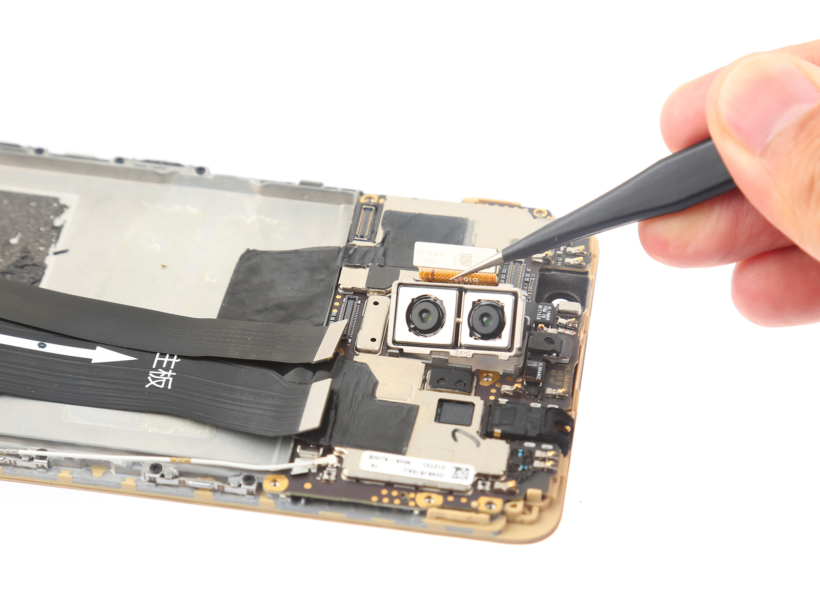
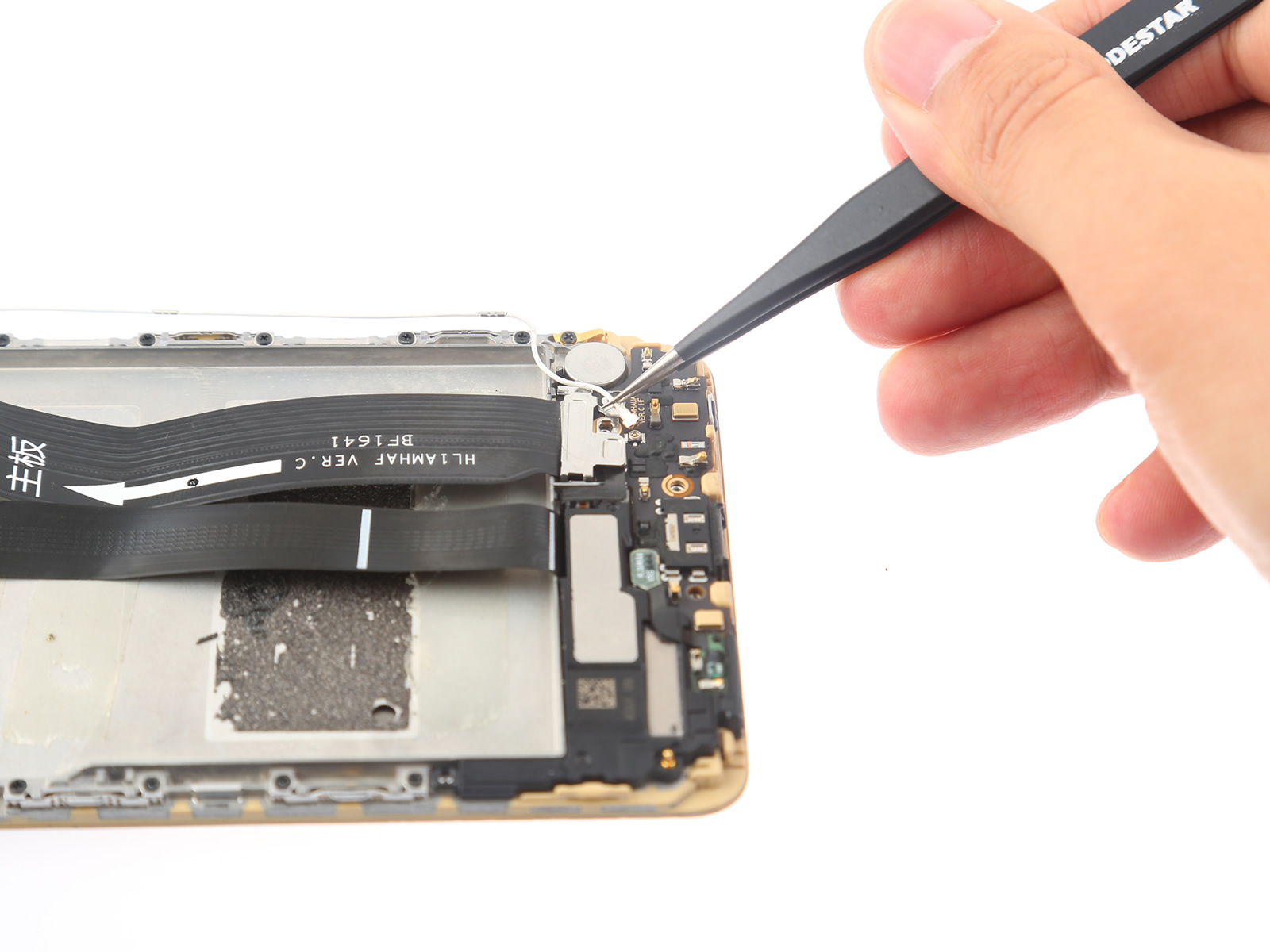
Disconnect the antenna cable from the motherboard.
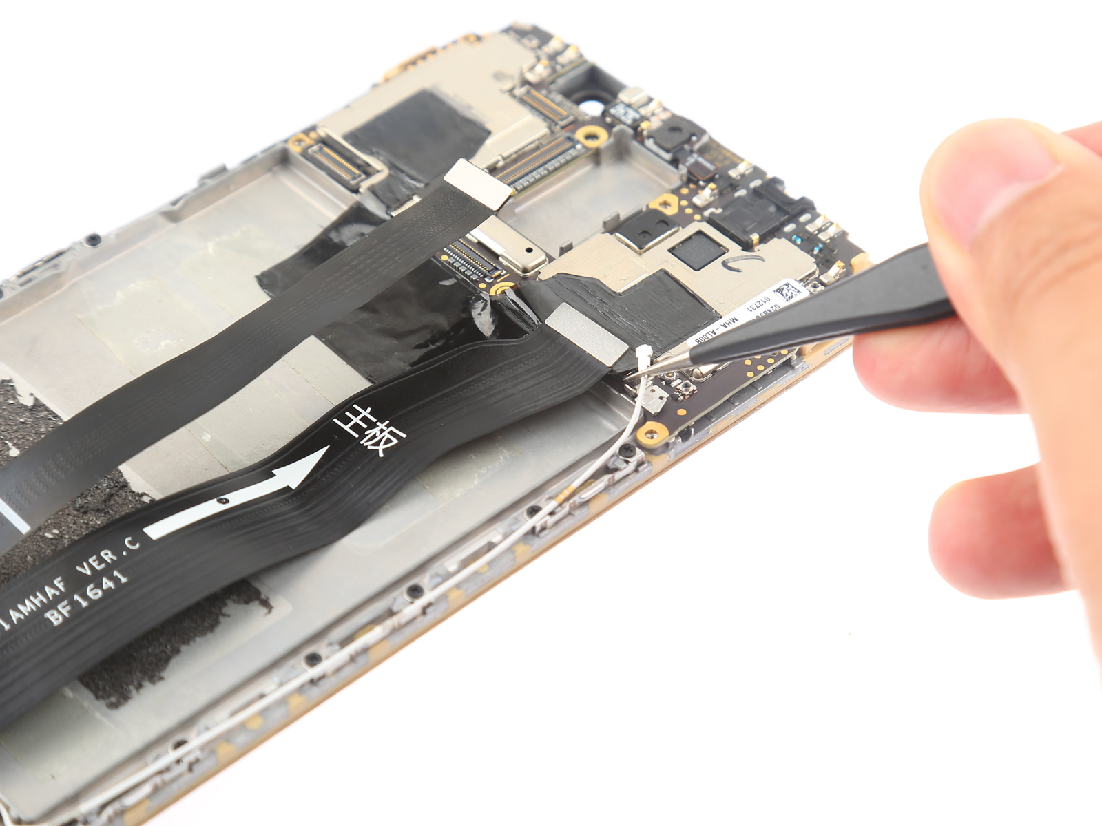
Lift the motherboard and remove it.
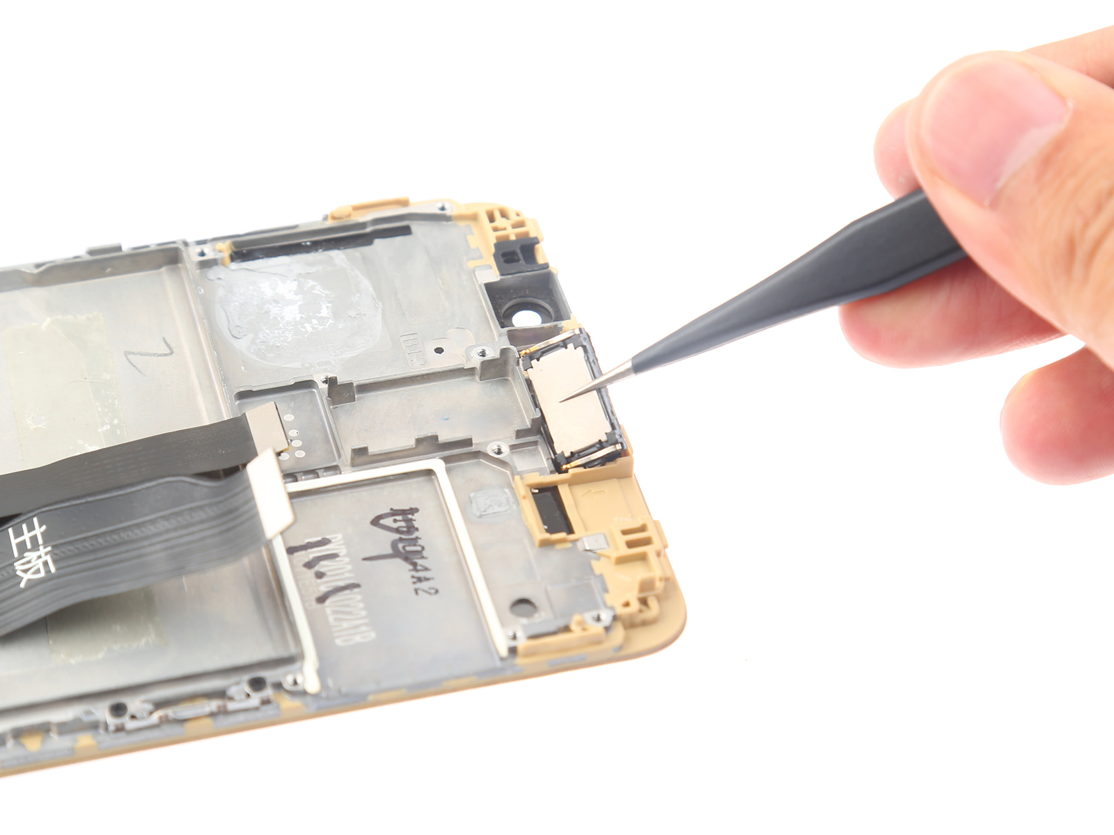
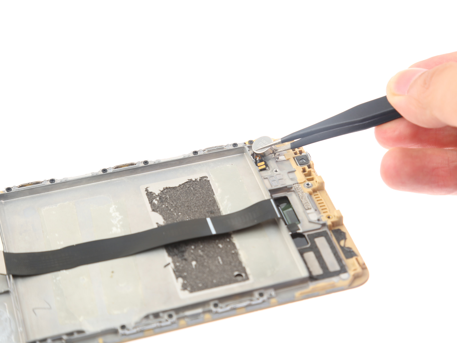
7. Remove the light distance sensor
Lift the light distance sensor with tweezers.
The light distance sensor is secured to the middle frame with glue.
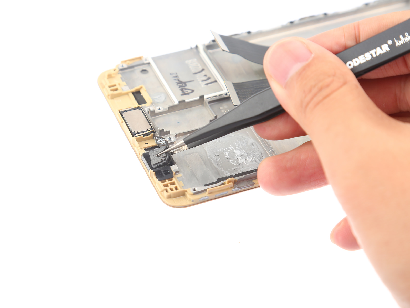
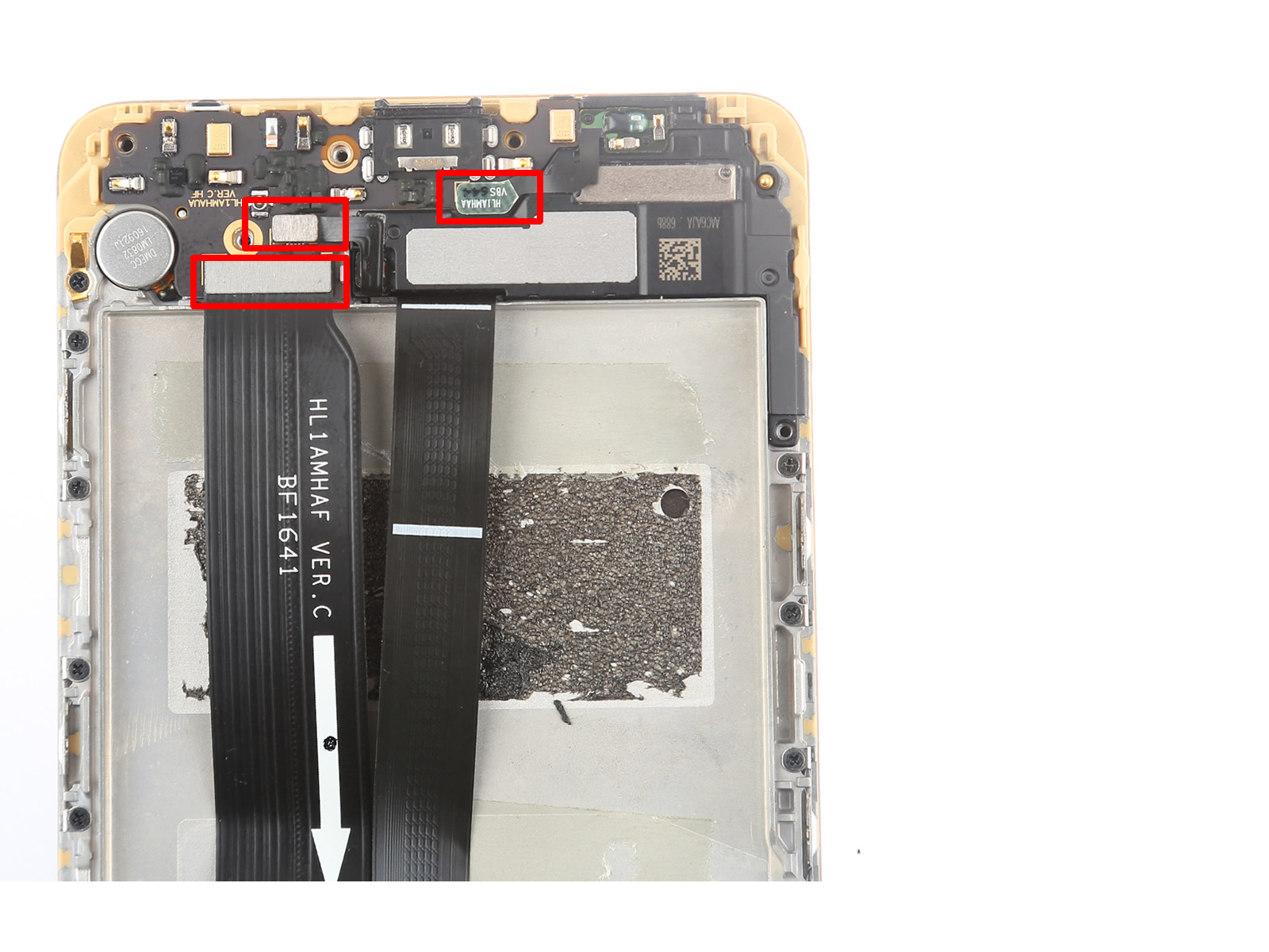
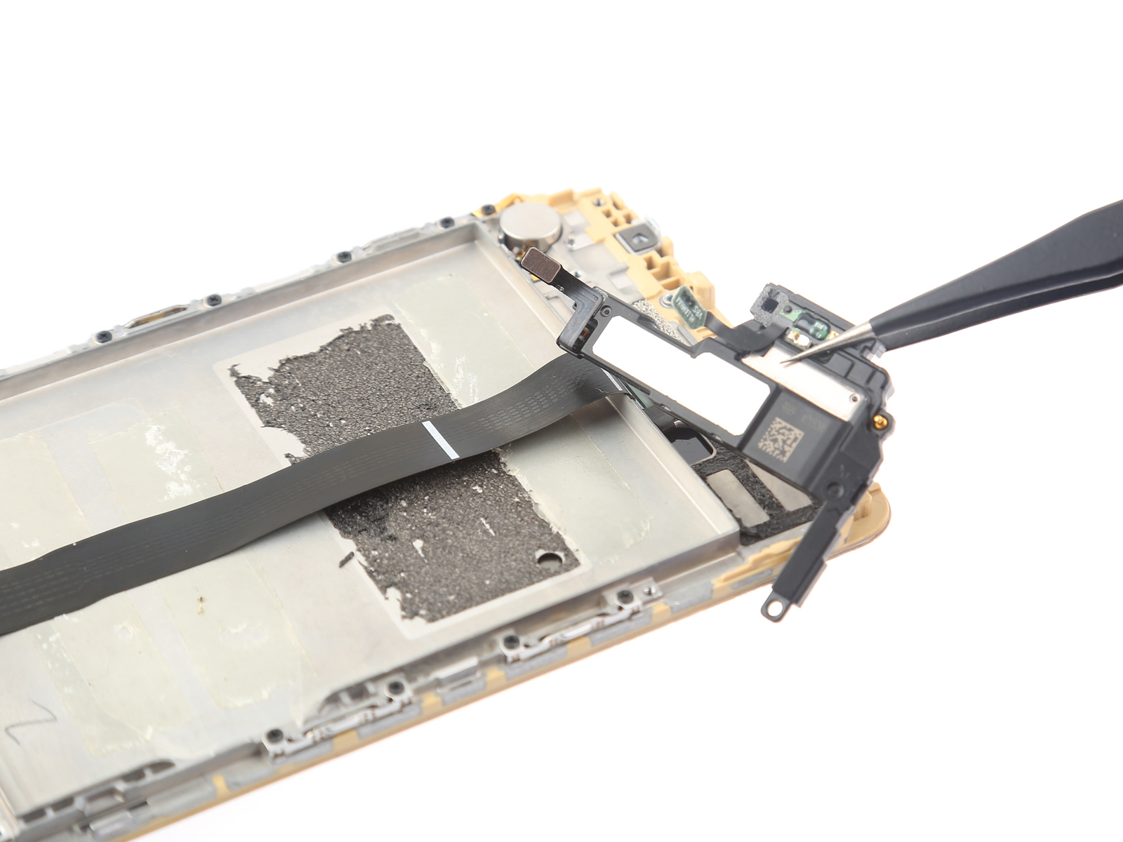
8. Remove the earpiece speaker
Lift the earpiece speaker with tweezers. The earpiece speaker is secured to the phone body with glue.
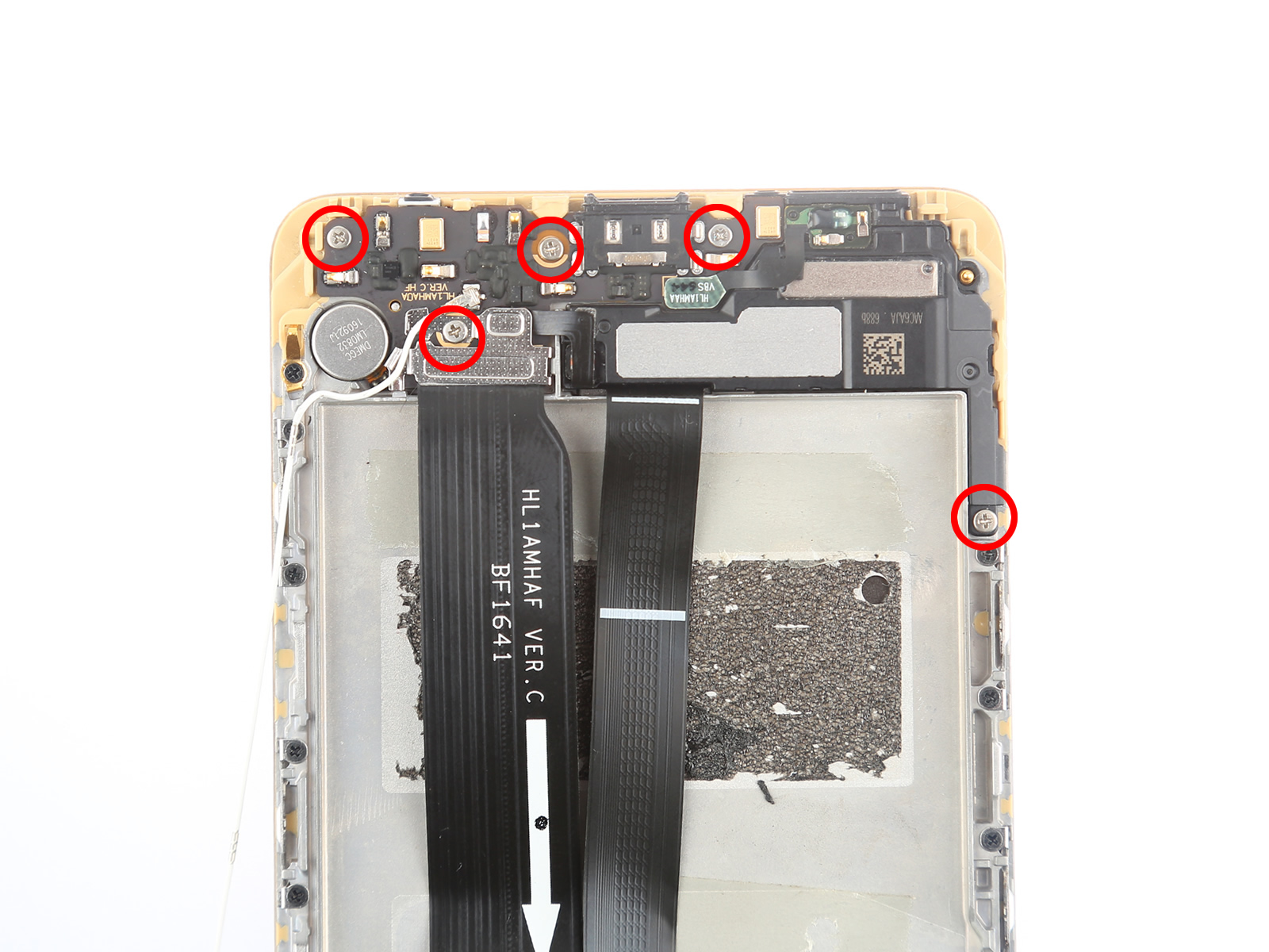
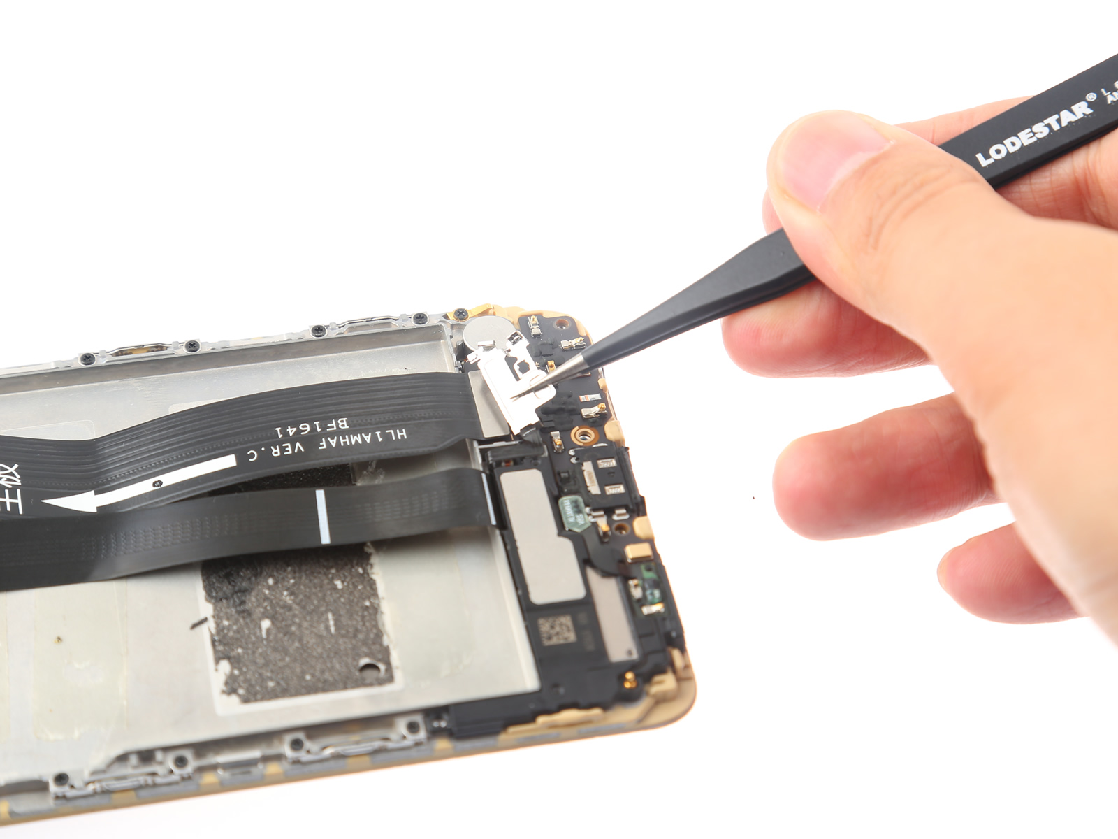
9. Remove the USB Type-C port board
Remove the five screws securing the USB Type-C port board and the loudspeaker.
Unplug the antenna cable. Now, you can remove the antenna cable from the phone.
Remove the metal plate that secures the main FPC.
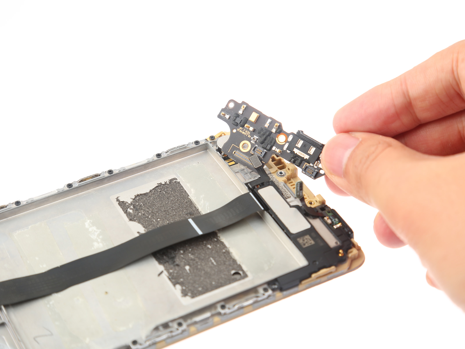
Disconnect the three cables from the USB board.
Lift and remove the USB Type-C port board.
10. Remove the loudspeaker
Insert a pick under the loudspeaker and lift it.
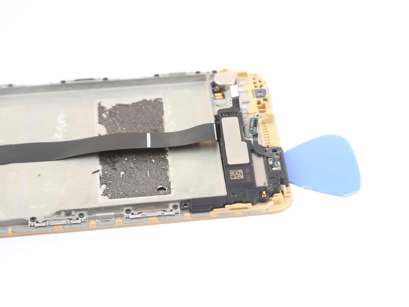
Now, you can remove the loudspeaker.
11. Remove the vibrating motor
Lift the vibrating motor with tweezers. The vibrating motor is secured to the phone body with glue.
If you are not a repair technician, we recommend purchasing a display assembly with the frame, as this will make replacing the display assembly easier.