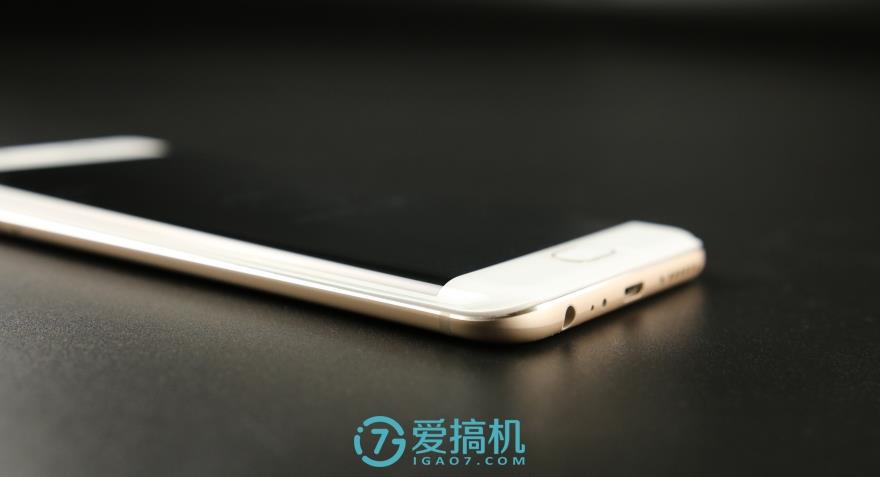
Vivo Xplay6 was launched in November 2016. It has a 5.46-inch touchscreen display with a resolution of 2560 x 1440.
The Vivo Xplay6 is powered by a quad-core Qualcomm Snapdragon 820 processor with 6GB of RAM. The phone has 128GB of internal storage, which cannot be expanded. The phone features a 12MP primary camera on the rear and a 16MP camera for selfies.
The phone runs Android 6.0 and is powered by a 4080mAh non-removable battery. It measures 153.60 x 73.40 x 8.20 (height x width x thickness) and weighs 178g.
The connectivity options include Wi-Fi, GPS, Bluetooth, FM, 3G, and 4G. The phone’s sensors include the proximity sensor, accelerometer, ambient light sensor, and gyroscope.
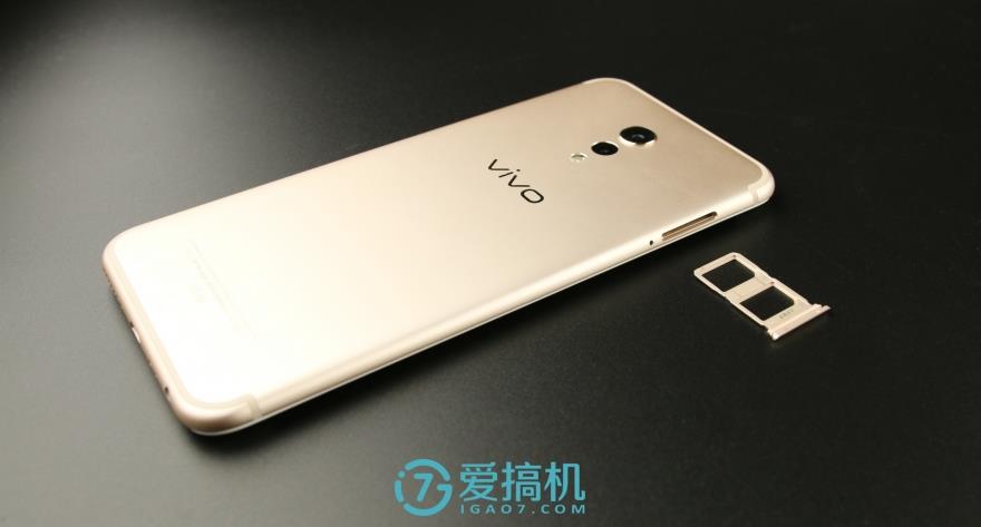
Before starting the disassembly, the first step is to remove the SIM card tray to prevent damaging the body during the process.
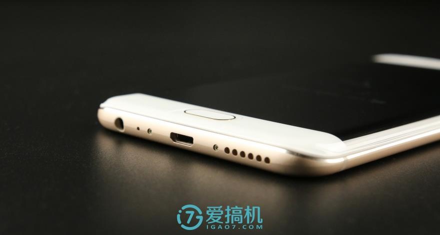
Remove the two screws beside the Micro USB port.
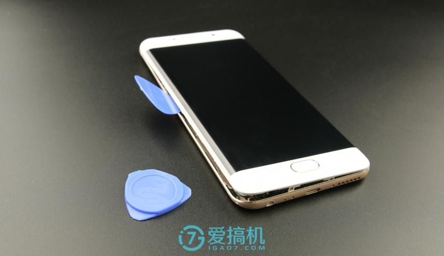
The double-curved glass is bonded using white gaskets and then secured with the metal back cover.
Insert a guitar pick between the back cover and body and slide it along the edge of the body.
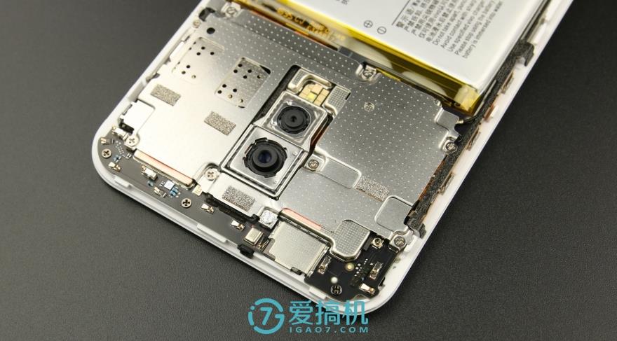
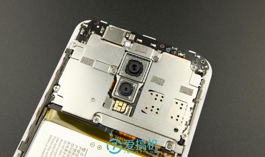
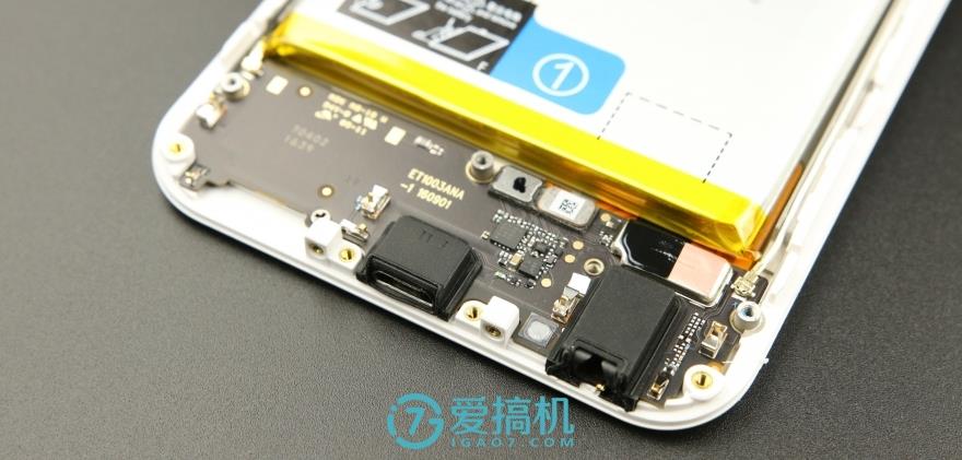
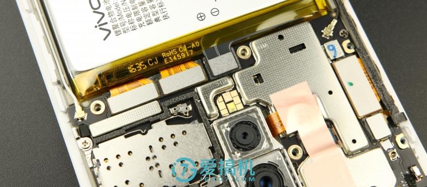
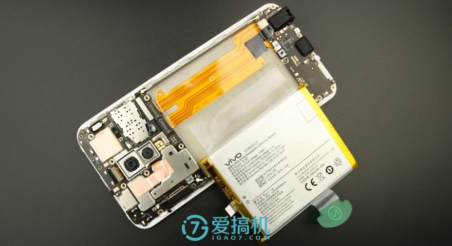
After removing the back cover, you can access the motherboard, battery, and other internal parts. The motherboard was covered with a metal shield.
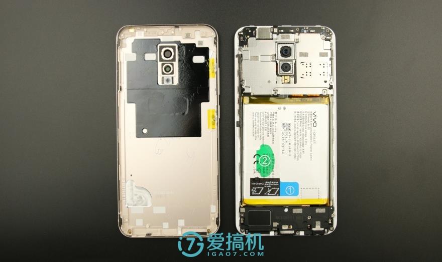
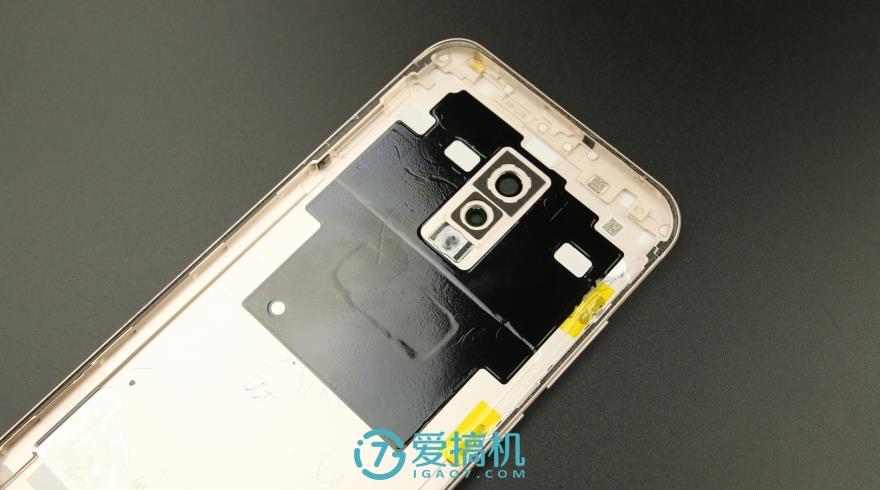
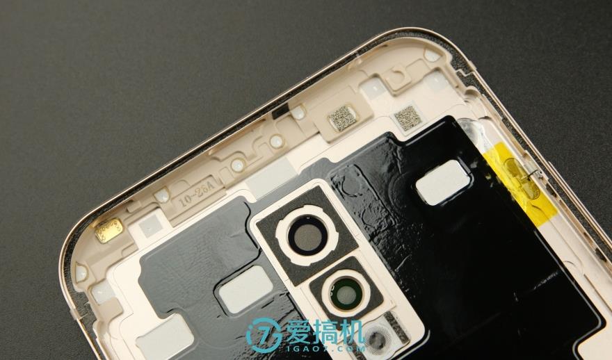
The inside of the back cover is covered with a large area of graphite thermal paste, but no NFC antenna is visible, which may indicate that the device still lacks NFC functionality.
The back cover and the middle frame are combined with a rubber strip, which not only makes the body tighter but also prevents dust from entering the body.
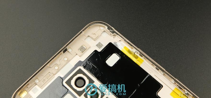
The inner edge of the back cover has some antenna contacts.
The motherboard is almost entirely covered by a metal shield.
The internal structure continues the more common three-part design. But after disassembly, we discovered another mystery: the complexity of this phone’s design far exceeds that of any previous mobile phone.
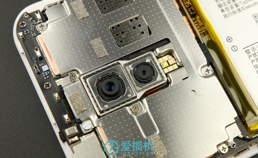
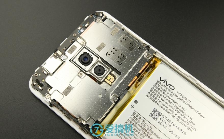
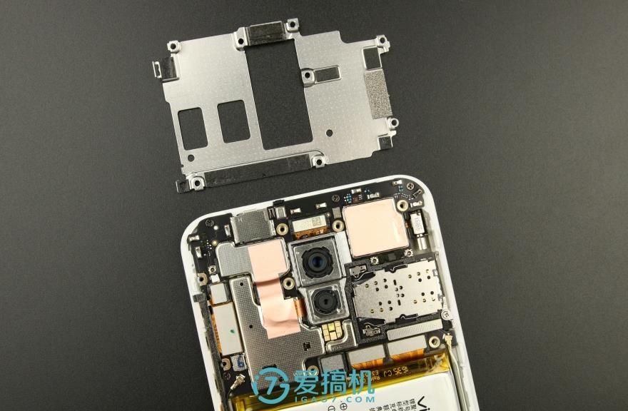
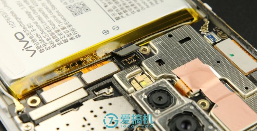
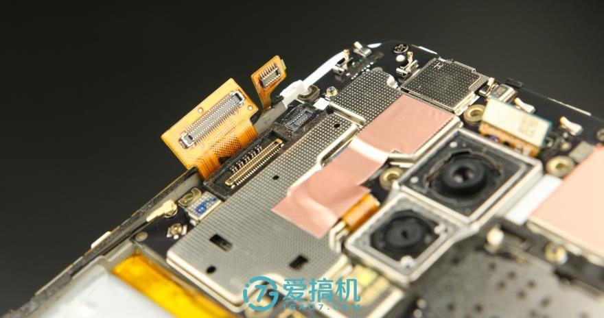
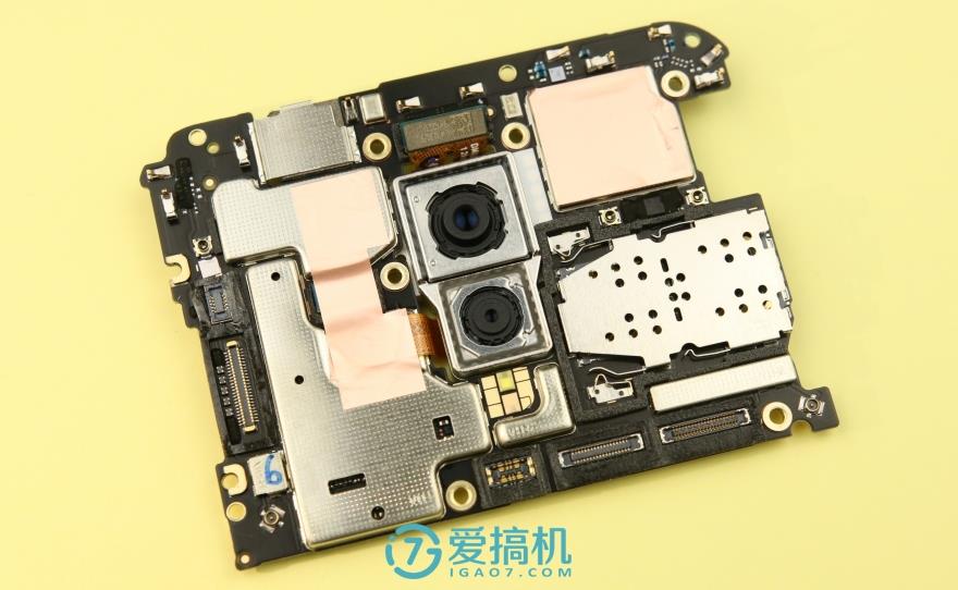
The camera module is located in the center of the motherboard, and two cameras are mounted on a separate metal module. The flash is installed on the motherboard.
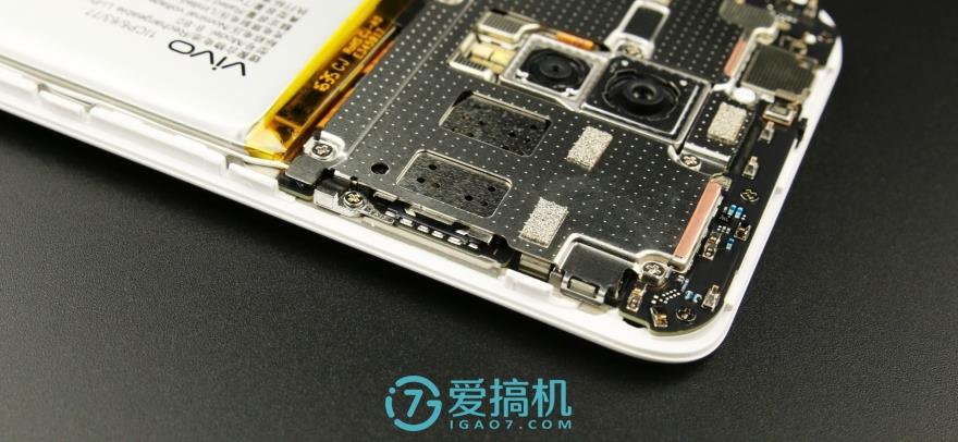
The motherboard has some metal contacts.
The SIM card slot is also covered by a metal shield.
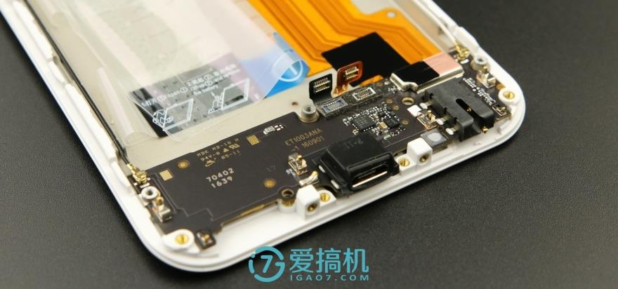
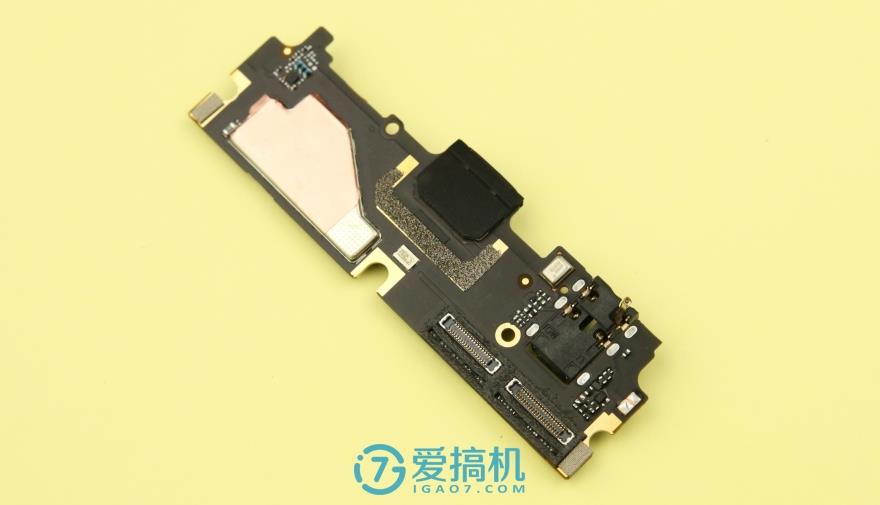
The bottom is the sub-board, which is secured with a plastic plate. From left to right, respectively, are the speaker, Micro-USB port, microphone, and 3.5mm headphone jack.
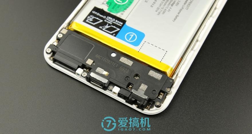
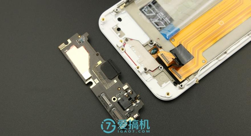
Removing the plastic plate reveals the sub-board, with the speaker located on the plate and connected to the sub-board via contact points.
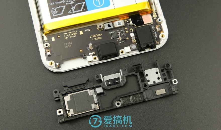
The sub-board is relatively simple, with fewer chips, and features two cable interfaces on the front.
First, remove the metal shield; the battery cable is located underneath it.
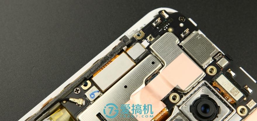
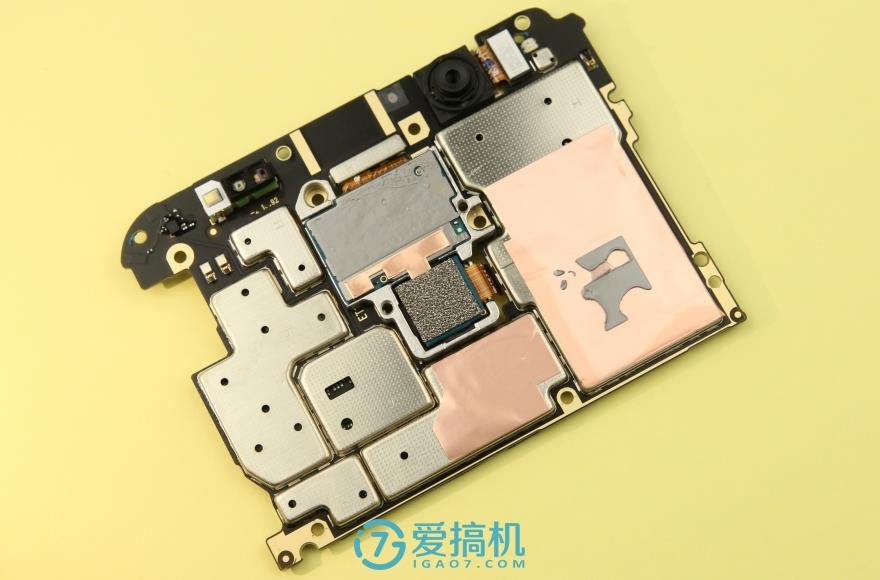
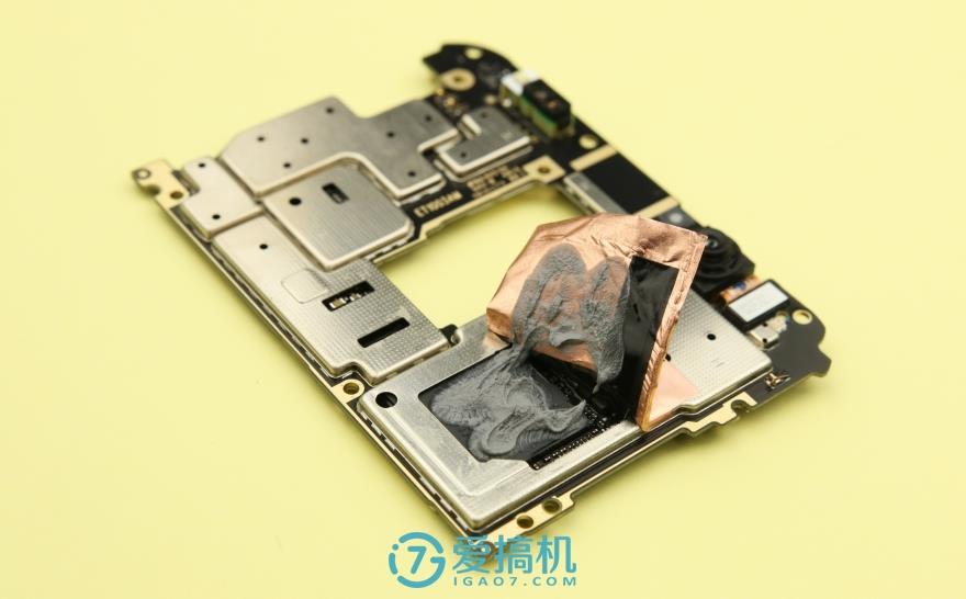
Unscrew the screws to remove the metal shield. We can see that most of the main chips on the motherboard are covered with a metal shield, and part of the shield is covered with copper foil to aid in heat dissipation.
There are some cables on the front of the motherboard. We will be removed one by one.
First, disconnect the battery cable to prevent circuit damage from short circuits.
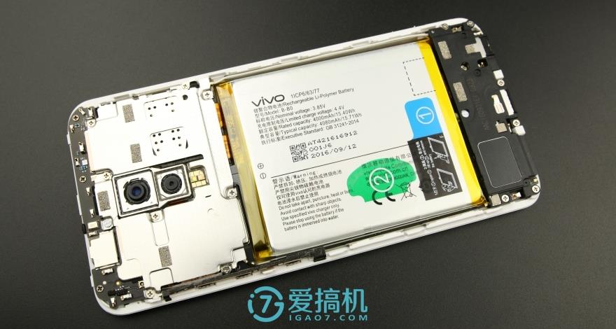
The lithium polymer battery has a capacity of 4000mAh and a nominal voltage of 3.85V.
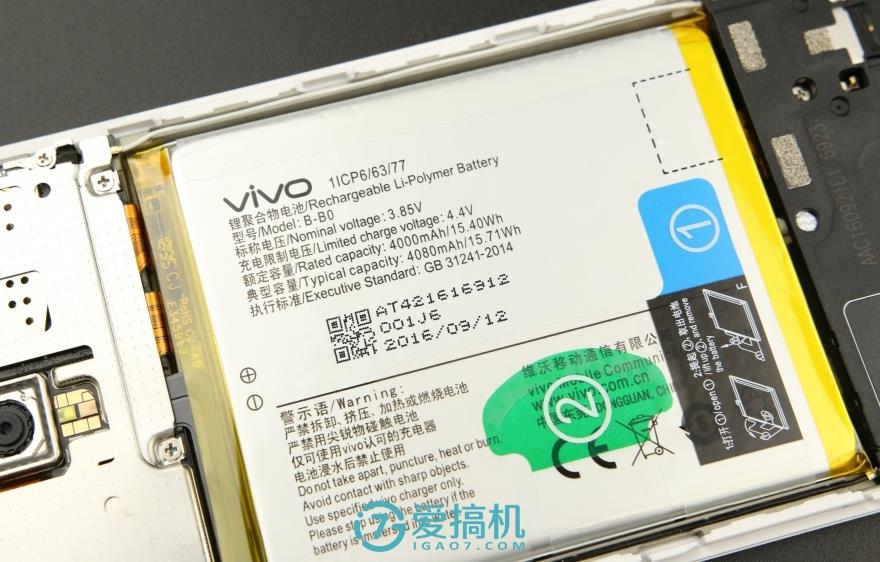
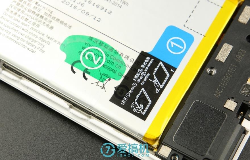
The battery is secured on the middle frame using double-sided adhesive. First, pull label 1, and then pull label 2. Then, you can easily remove the battery.
Disconnect all cables from the sub-board.
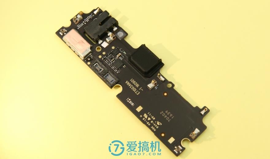
The back of the sub-board has a metal shield and is covered with copper foil.
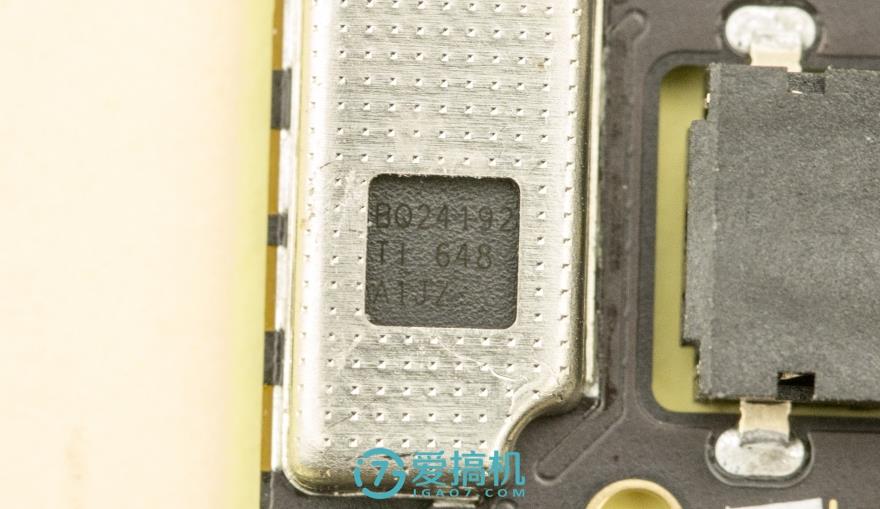
The TI BQ24192 is a battery charger IC.
Disconnect all cables from the motherboard and remove all screws.
When the motherboard is removed, the metal shield covers a large area of copper foil connected to the middle frame through thermal paste. This design can more effectively conduct heat to the middle frame, thereby assisting in heat dissipation.
The front of the motherboard also has two large copper foils.
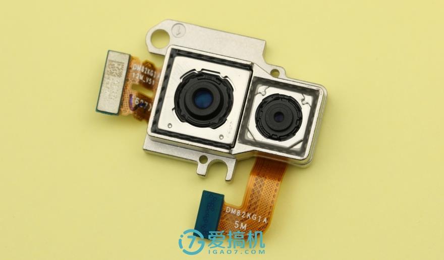
The Xplay 6 features a dual rear camera setup with a 12MP primary sensor and a 5MP secondary sensor. The 12MP main camera uses a Sony IMX362 sensor, supports four-axis optical image stabilization (OIS), and has an f/1.7 aperture. Both cameras are secured to the metal frame with glue.
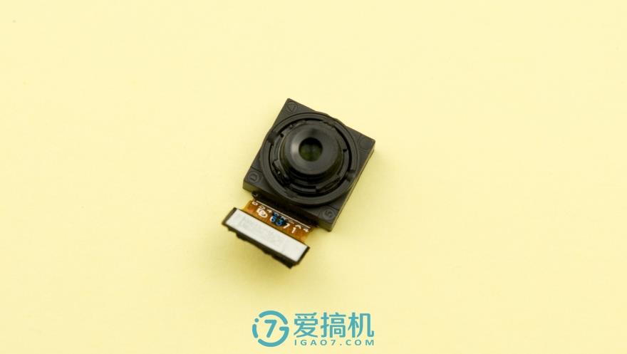
It features a 16MP front camera with a soft selfie timer and a soft light secured to the motherboard.
After removing the copper foil on the back of the motherboard, you can see the SOC chip covered in a lot of thermal grease.
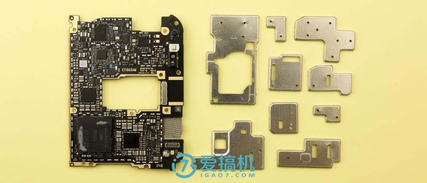
Remove all metal shields from the motherboard.
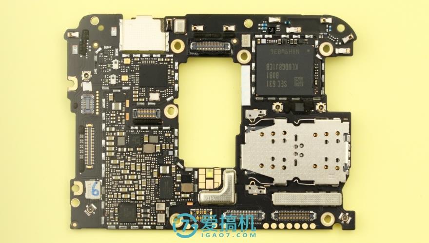
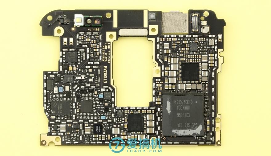
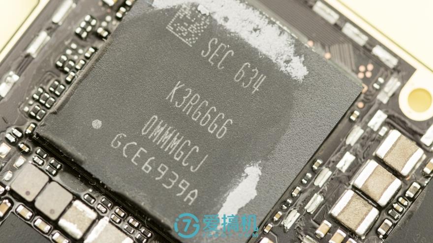
The Samsung K3RG6G6 0MMMGCJ LPDDR4 memory chip is located on the back of the motherboard. It has a capacity of 6GB and is packaged with a Qualcomm Snapdragon 820. This chip is manufactured using a 14nm FinFET process and features an Adreno 530 GPU.
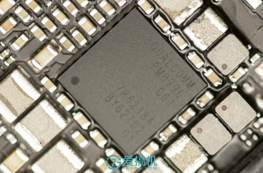
Qualcomm PM8996 power management IC
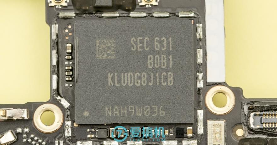
Samsung KLUDG8J1CB-B0B1 flash memory chip
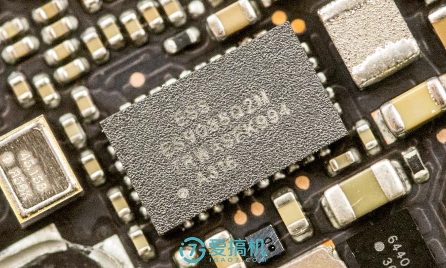
ES9038Q2M Audio chip
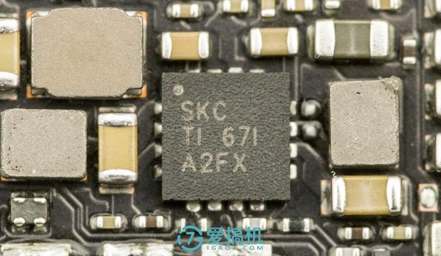
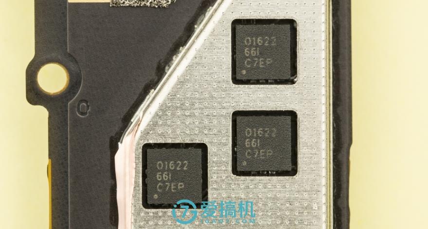
Like its predecessor, the Xplay6 also uses a three-op-amp design, but it has been upgraded to the OPA1622 audio amplifier from Burr-Brown, a brand of Texas Instruments. This chip is an upgraded version of the OPA1612. The audio circuit design of the Xplay6 is quite distinctive: the three op-amp chip components are placed on a sub-board and connected to the main board via cable.
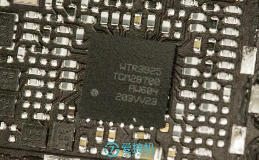
Qualcomm WTR3925 LTE transceiver
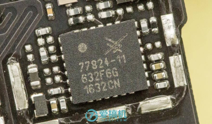
Skyworks 77824-11 LTE power amplifier module
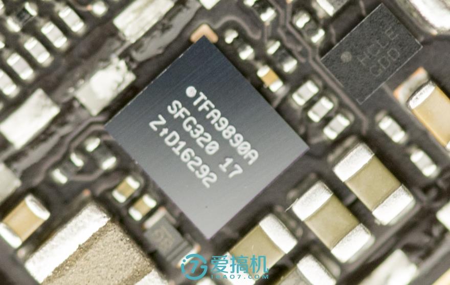
The NXP TFA9890A is an audio chip primarily for Smart PA audio solutions with Class-D amplifiers. Smart power amplifier technology can significantly enhance output power and improve audio quality.
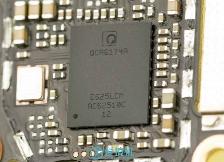
Qualcomm QCA6174A Wi-Fi and Bluetooth integration module
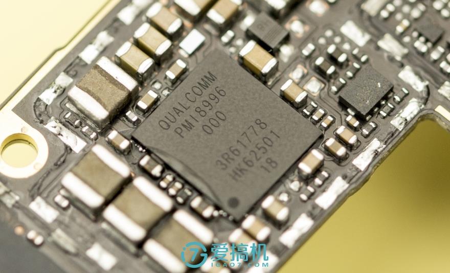
Qualcomm PMI8996 Power Management IC
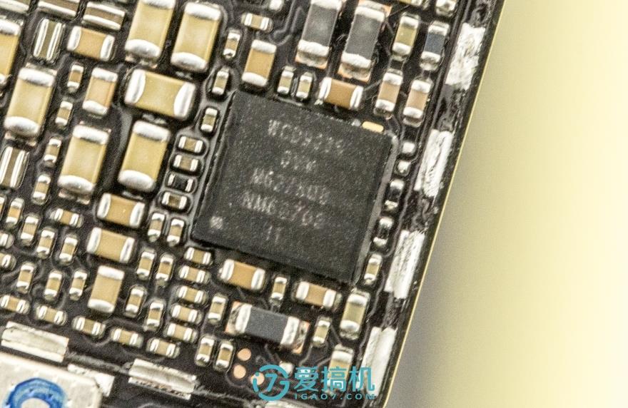
Qualcomm WCD9335 audio decoder chip
RFMD RF7460 multi-mode multi-frequency PA module