For making thin and light laptops, many manufacturers are now heading toward soldered memory, which no doubt helps reduce the thickness while making it almost impossible for regular users to upgrade memory. To increase RAM capacity, your only option is to spend more money on a high-capacity RAM variant. In this post, we will discuss how to upgrade the onboard memory on these kinds of laptops.
Before upgrading the onboard RAM, you must determine the maximum RAM capacity your laptop supports. Have a look at this article before proceeding to the next step. In our case, we used the ASUS Zenbook UX430UN. It has 8GB soldered RAM and supports up to 32GB of memory.
At the beginning of this process, we must know the SPD information of the RAM. This information is stored in the BIOS for onboard memory. Software like AIDA64 can’t help in this scenario.
What is Memory SPD?
Before going further, you must know what SPD is. It is a re-writable EEPROM on the RAM stick. It typically includes the record of important information, such as the RAM’s manufacturer, Operating Frequency, Operating Voltage, Read/Write Speed, Memory Capacity, and other related specifications. SPD information is generally written into the EEPROM Chip by the RAM’s manufacturer (as per the actual performance of the RAM) before the RAM leaves the OEM factory.
Detailed steps for upgrading the onboard RAM on a laptop
Step 1. Check the RAM Chip Supported By Your Laptop
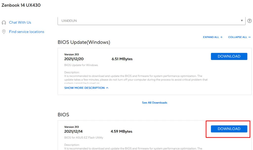
First, head toward the official website of the laptop’s manufacturer (asus.com, in our case) to download your laptop’s BIOS file. After downloading, use Winzip to decompress this file. It is possible that the decompressed file doesn’t have a .bin extension, but no matter what extension it has, change the file’s extension to .bin and open it with WinHex software (which can be downloaded from WinHex.com).
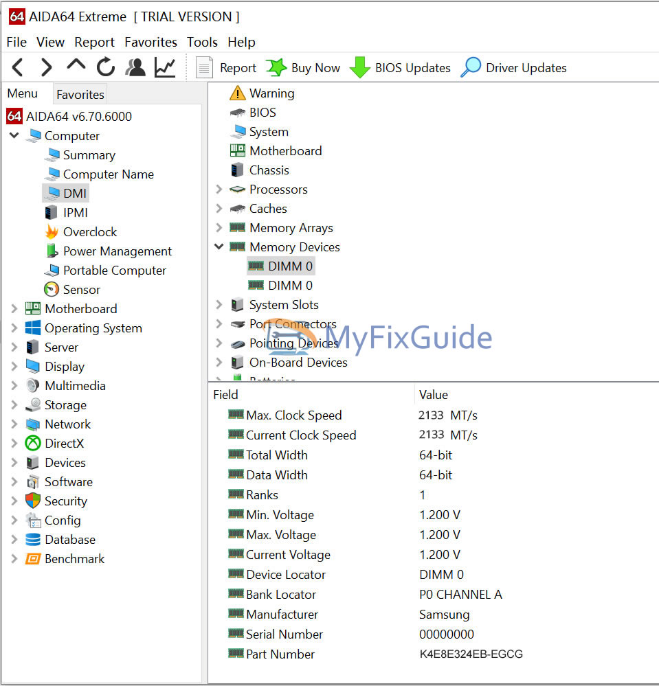
Then, open AIDA64 or a similar software to check the RAM’s model number. In our case, the RAM has the following model number: K4E8E324EB-EGCG. Copy this text, paste it into WinHex, and click search. All the other RAM your laptop supports will be displayed on the screen.
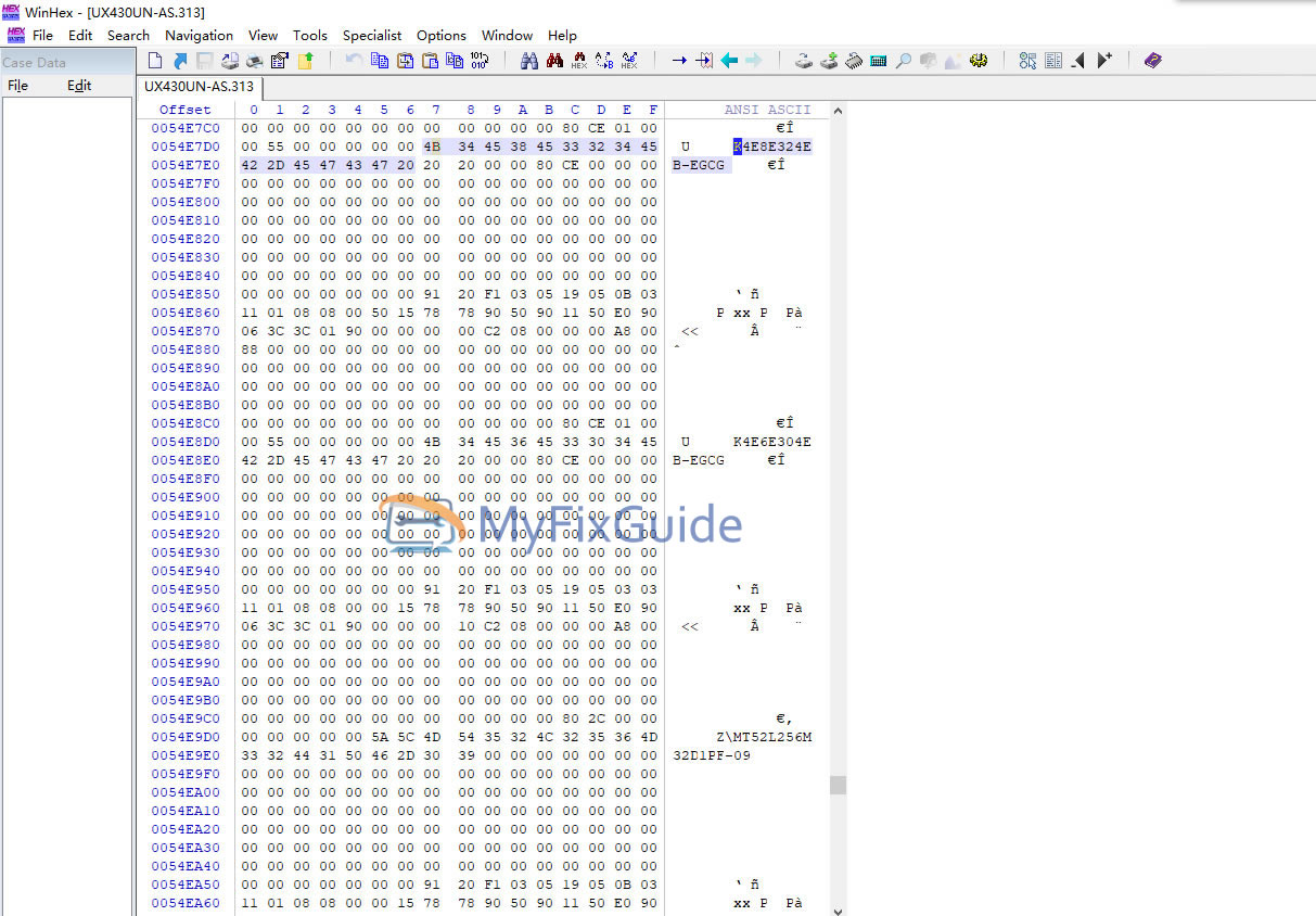
The display information is the same SPD information that we discussed above. The UX430UN supports six types of memory chips. Now, you can select any one of these RAMs based on your needs. If you tried to solder other RAM chips, the computer will probably not recognize them.
The Asus UX430UN supports six memory chips
K4E8E324EB-EGCG
K4E6E304EB-EGCG
MT52L256M32D1PF-09
MT52L512M32D2PF-09
K4EBE304EB-EGCG
MT52L1G32D4PG-093
Step 2. Purchasing Memory Chips
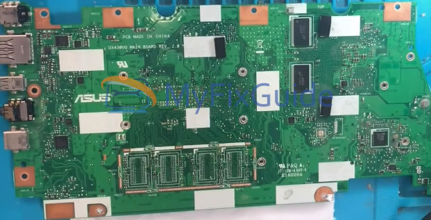
When checking with AIDA64, it indicates that this laptop has two memory channels. Each channel consists of four 1GB memory chips, and you can also remove the motherboard from the laptop to see the number of memory chips (there are a total of 8 memory chips on the UX430UN motherboard; four chips are on the front of the motherboard, and the other four are on the back of the motherboard). Our goal was to upgrade the memory capacity to 16GB, so I purchased 8 K4E6E304EB-EGCG (2GB) chips to achieve a total of 16GB of memory.
Now, the question is, how much RAM capacity should you buy? That depends on your personal needs. This notebook also supports K4EBE304EB-EGCG, a 4GB memory chip, which means the UX430UN supports up to 32GB of memory. Please note that you must purchase new memory chips. On many E-Commerce platforms, profiteers are selling used memory chips.
Note: When purchasing, let the seller install solder balls on the memory chips.
Step 3. Required Tools, DIY Ability, and Risk Tolerance
Before purchasing the memory chips, please read the following important points and decide whether you are eligible to proceed. If not, then doing this entire procedure isn’t recommended at all. It would be better to take the laptop to a professional or a technician for repair.
- Bitmap (If you update the BIOS SPD instead of changing the memory configuration resistors, you don’t need a bitmap)
- Required Tools: Heat Gun, Soldering Iron, Multi-meter, and Small Tweezers are needed. Solder, Soldering Oil, and Flux are also required.
- Do you have proper DIY knowledge?
- Do you have the courage to accept failure and the ability to take risks?
If any trick is accidentally lost, the consequences of this failure include, but are not limited to, CPU Failure, a capacitor or resistor that you can’t see, costly repairs, or the need to replace a new motherboard.
Step 4. Remove the Memory Chip
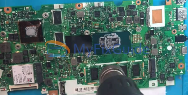
Before starting the whole process, rub your hands to discharge static electricity from your body. To disassemble the laptop, unplug the battery and remove other components, such as the keyboard, CPU fan, SSD, and LCD screen. These are the parts that need to be removed when disassembling the motherboard. Once the motherboard is separated, find out the location of the soldered RAM. It is highly recommended that you take some photos of the motherboard at this point.
Before further operation, properly observe the welding position of the memory. Although most of the notebook’s motherboard has a frame on the RAM area, the new memory can be soldered within the frame. However, in our case, the frame size is quite large, so accurate positioning of RAM is essential. After the correct positioning, ensure that the solder balls can be easily absorbed into the solder joints on the motherboard after the soldering has melted. It will increase our success rate.
Further, it can also be seen that there is a white dot on the lower left of the memory chip and a white corner mark on the motherboard, both of which indicate the correct installation area. Installing the memory chip in the wrong direction can cause problems and damage the motherboard or memory chip. Also, taking an image of the capacitor and resistor positions around the memory can help prevent the wind gun from blowing too much while disassembling.
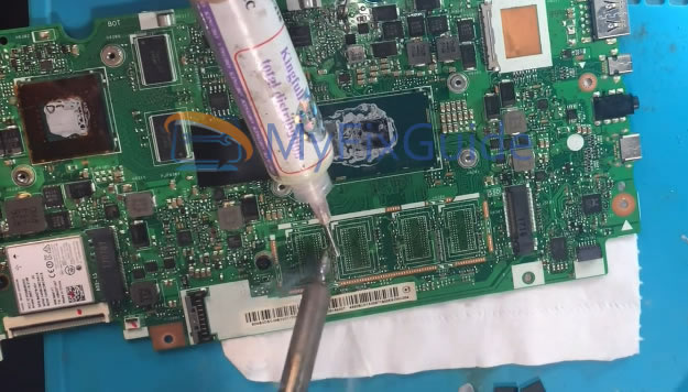
Now, apply a small amount of soldering oil to the gap above and below the memory chip. At the top, it will dissipate the heat for the memory chip. At the bottom, it will help make the pads heat more evenly and make them easier to disassemble. Set the hot air gun temperature between 300-350 degrees Celsius and the wind speed to a bit high. At first, evenly heat several memory chips to prevent local thermal expansion and contraction. It is expected to blow for a while. When the soldering oil starts having bubbles under the memory chip, and the chip also starts to move with tweezers, properly remove the memory chip with the tweezers, but remember not to lift it with tweezers. Otherwise, you may damage the capacitors and resistors on the motherboard. As we have used the heat gun on the memory chip, avoid touching it with your bare hands as it will be very hot.
Note: Wait until the memory chip can be gently pushed before clipping it off from the motherboard. Forced removal of the chip may damage the chassis.
Step 5. Cleaning the chassis
After removing all memory chips, clean up the chassis (while the motherboard is hot) before the motherboard’s temperature gets too low. Try to melt a small amount of solder on the soldering iron, place it on the chassis, and gently push it around. This will help in sucking all the solder on the wire.
Step 6. Solder the New Memory Chip to the Motherboard
After completing the previous process (removing old RAM), it is time to install the new RAM with a higher capacity. Apply some solder paste to the chassis, which will stick to the memory chip and prevent it from being blown away by the hot air gun. Also, check it carefully before placing the new memory chip on the chassis to see whether it is intact.
Now, blow the chassis with a heat gun, set the air speed to low. You will need to ask the seller if it’s a high-temperature tin or a low-temperature tin. Generally, a temperature between 250 °C and 300°C would be acceptable. Blow it for a while, and then you can move the memory chips with tweezers. If the memory chip is easily shaken, the solder balls below have melted. Also, keep in mind that the range and strength of dialing don’t need to be very large. If you place the balls in an accurate position, the solder balls will also automatically move to the correct position (where they should go after melting). Just give it a little dialing help.
Now, after installing the new memory on the motherboard, do not assemble the laptop at this point. It is not recommended at all to boot up the laptop in a hurry. If someone does this, the laptop will still show the previous memory size and model. This happens because the laptop reads hardware information from the BIOS at boot time (especially memory information, since its memory SPD information is only stored in the BIOS) and then proceeds with a further boot process.
The SPD file in the BIOS file (obtained from the official site) mentions that the laptop has six different memory chips. As we know, the manufacturer also produces the same model with varying RAM capacities (lower-end and higher-end variants). Now, the question is: How does BIOS know which (how much) memory is installed on the motherboard? At this stage, the BIOS only needs to detect the current in a few specific locations to find which memory chip configuration to use. This is the configuration resistor that is often seen. We will modify it in the next step.
Step 7. Modify Memory Configuration Resistors.
As mentioned in the last step, we now have to modify the memory configuration resistors. There are two ways to alter their configuration.
- Hardware Modification
You need to find the motherboard’s bitmap and search for the memory resistors’ names (on the bitmap) corresponding to the motherboard’s position. After seeing the exact location of the configuration resistor, adjust the resistor position in the bitmap.
I tried to do the process on the UX430UN. Unfortunately, we couldn’t find the bitmap, so we used the second method, which is to modify the SPD information of the memory in the BIOS.
- Software Modification
The second method is to modify it with software. We will modify the SPD information of the memory in the BIOS. Before proceeding, it is worth mentioning that this method has a disadvantage: it doesn’t allow the user to update the BIOS. Otherwise, updating the BIOS will lead it to restore the original memory configuration.
Navigate to the SPD Information section in the BIOS, where all memory configurations will be displayed. It doesn’t matter at all if you understand the hexadecimal or not. All you need to do is find which current signal represents the memory configuration. After identifying, we can change the hexadecimal characters to 0 0 1 current, representing.
We should observe each segment of memory configuration information properly, starting with 91 20 characters, and then swap the two strings of characters representing K4E8E324EB-EGCG and K4E6E304EB-EGCG.
After completing the modification, change the modified BIOS extension to the original one. Flash it into your notebook. Upgrading the BIOS in the future is not recommended except when you are willing to change the RAM’s SPD information again. The entire procedure is now completed. You can head to the PC Properties to check that everything is okay. The Benchmark software is also recommended to test if the memory is working properly.
I have a question. I have a UX325EA, and I did the exact same program. Only my UX325EA has 4 modules; the question is, when you switch modules, does it immediately refresh the BIOS, and if so, is it a download of the modified BIOS? Do you go directly to the BIOS MOSFET? Because my computer boots with a black screen when switching memory. Thank you!
Hey, I have a ZenBook 13 OLED UX325EA. I’ve been looking to upgrade my laptop RAM as well. Have you upgraded successfully?
Of course, the upgrade has been successful.
I have an X1 Carbon 10th gen, and how can I get the current soldered RAM SPD data?
Another question is, is it possible to flash RAM without disassembling or without an SPI programmer?
Hi, about the BIOS for RAM verification, I can’t find it in WinHex. Did you make any configuration changes to view it?
WinHex doesn’t need to be configured. You may have downloaded the wrong BIOS file.
Hi, I have an HP Laptop 15-fc0015nia (86Z53EA) with 4GB RAM. The RAM is soldered to the motherboard, but the maximum capacity says 16GB, so I want to know how to upgrade the RAM, and there are no other slots.