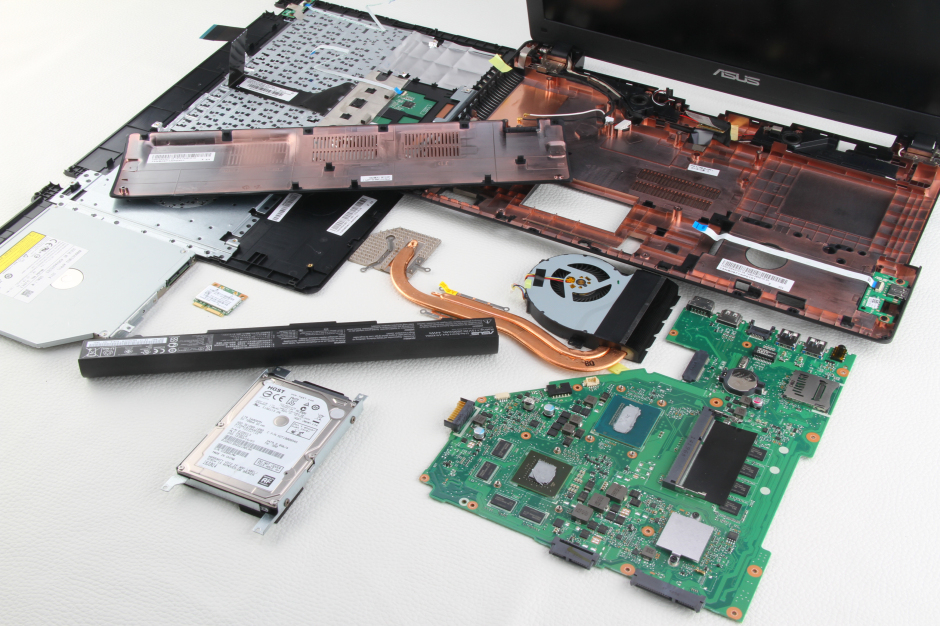
In this guide, I will explain how to disassemble the Asus A550JK to remove the hard drive, DVD drive, keyboard, palm rest, wireless card, bottom case, USB board, heat sink, cooling fan, and motherboard.
Want to stay connected to MyFixGuide.com? Follow us on Facebook to check out the latest teardowns.
Asus A550JK Specifications
CPU: Intel Core i7-4710H
Memory: 4GB (4GB × 1)
Memory type: DDR3L 1600MHz
Maximum Memory: 12GB
Hard drive: 1TB 5400RPM
Screen: 16:9, 15.6-inch LED screen, no-touch
Resolution: 1920×1080
Graphics card: NVIDIA GeForce GTX 850M
Graphics Memory: 2GB DDR3
Motherboard Chipset: Intel HM86
Operating System: Windows 8.1
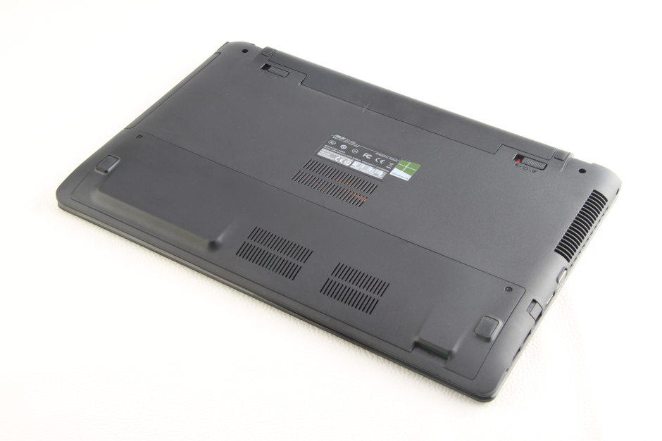
Unlock and remove the battery.
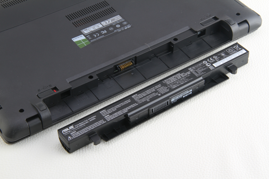
The Asus A550JK comes with a 2950mAh Li-ion battery. The Asus part number is A41-X550A.
Remove the two screws securing the service cover. Use a pry tool to lift the service cover from the SD card slot and remove it.
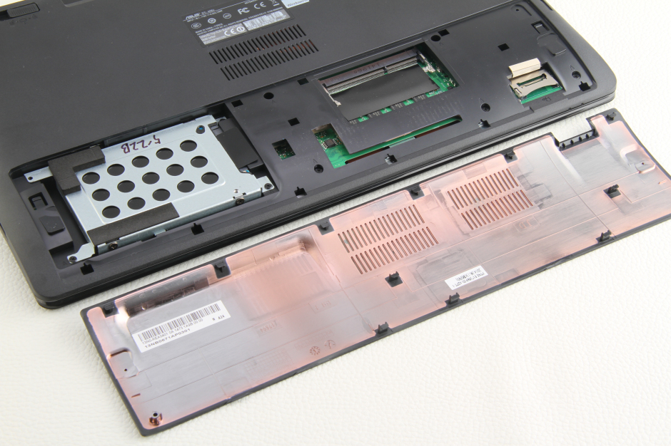
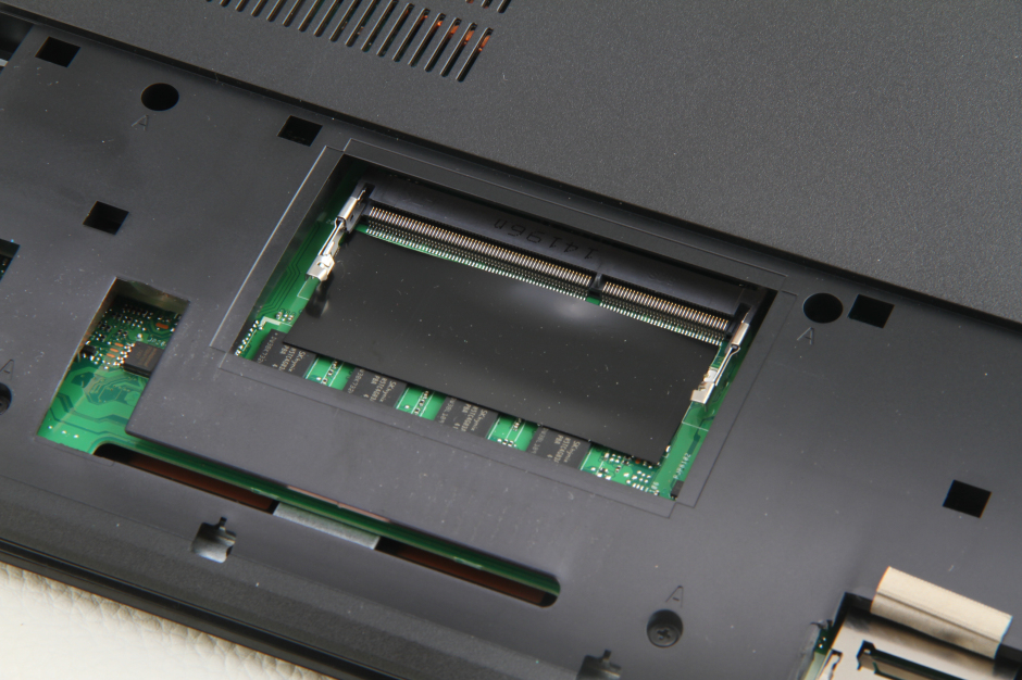
Under the bottom cover, you can see four memory chips soldered onto the motherboard and one empty memory slot. You can add a memory module to upgrade the memory.
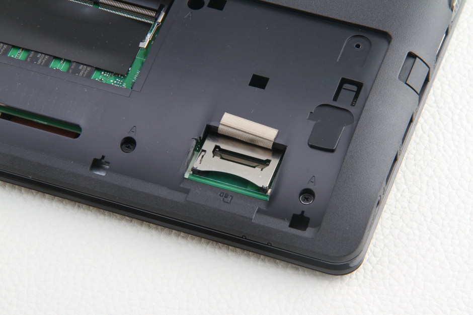
SD card reader
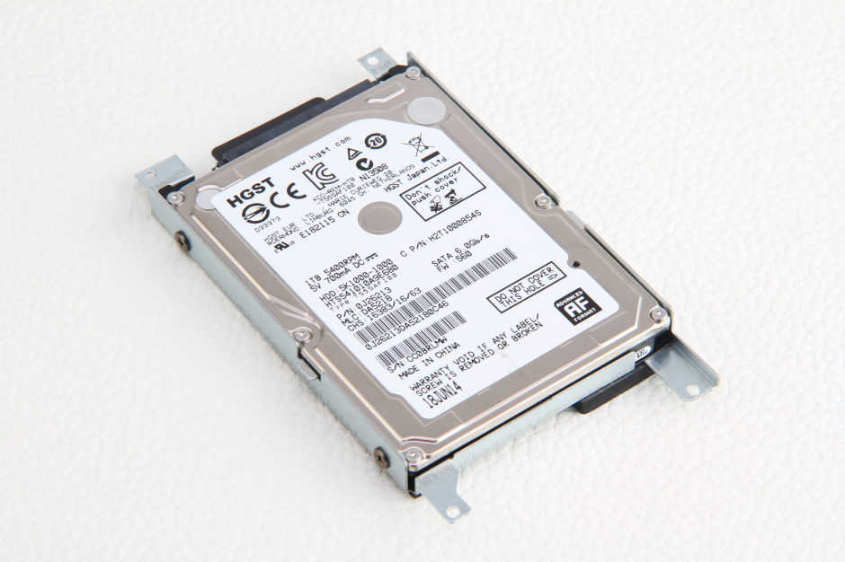
Remove the three screws securing the hard drive module. Lift the black tape and slide to the left.
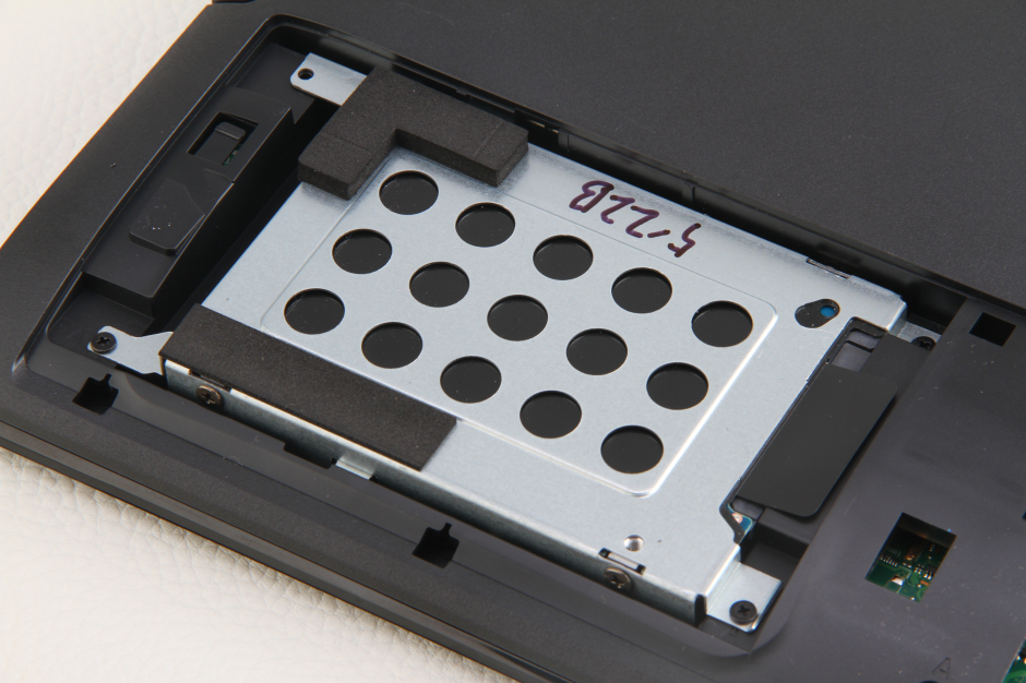
The laptop comes with a 500GB HGST hard drive.
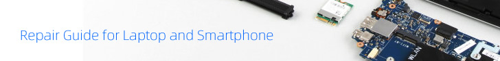
Remove all screws from the bottom case.
Turn over the laptop. Insert a plastic pry tool between the bottom cover and the palm rest. The palm rest has many clips to secure it to the laptop, and you need to slide the pry tool to release all the clips in order to remove the palm rest.
Disconnect the keyboard cable and touchpad cable. You can remove the palm rest.
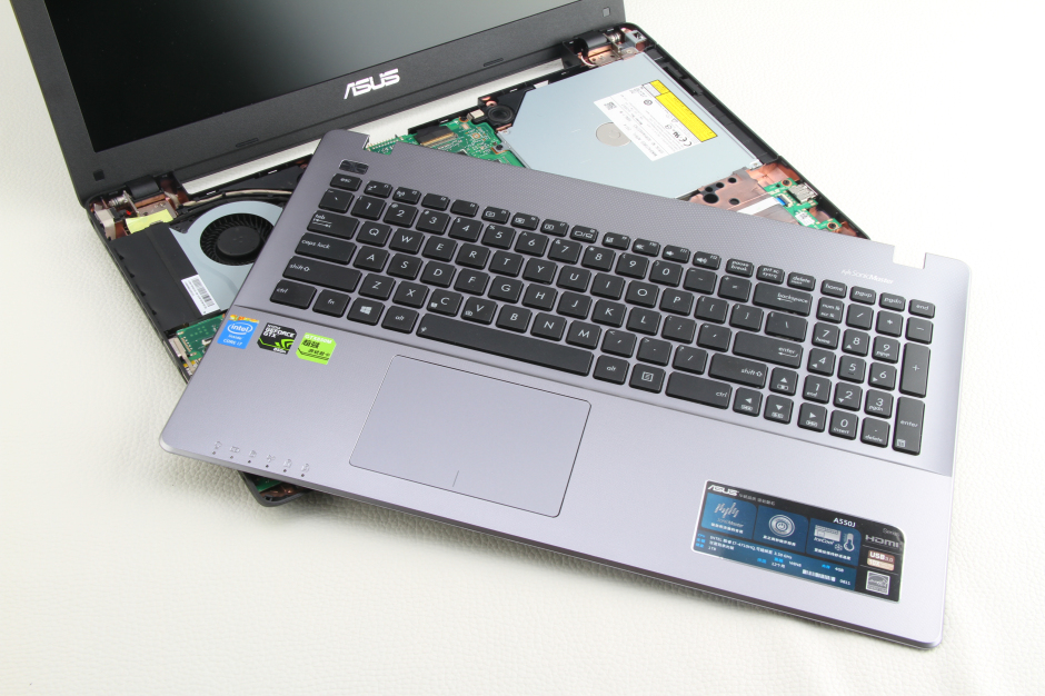
On the back of the palm rest, you can access the keyboard and touchpad. At this point, you can replace the keyboard.
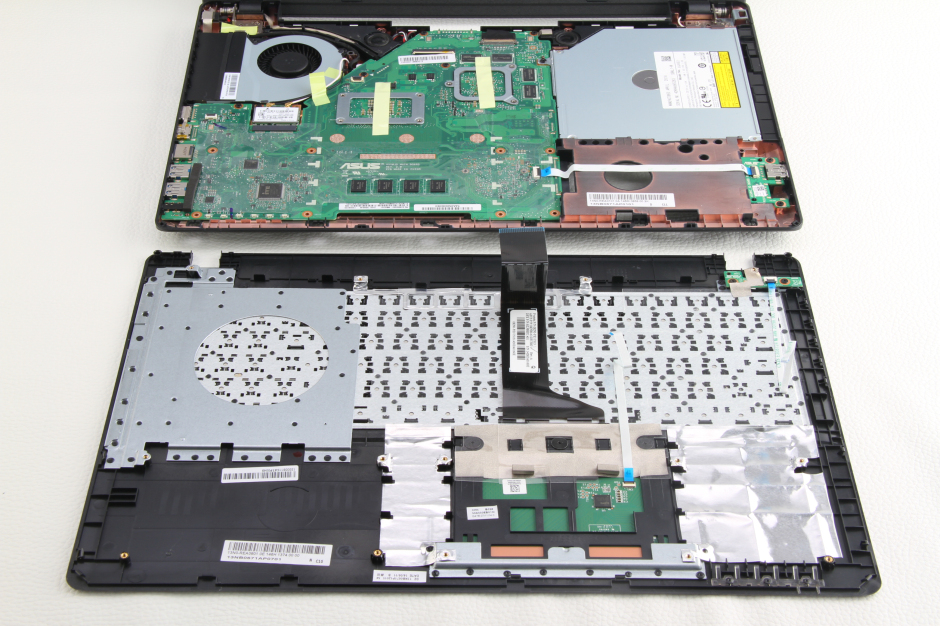
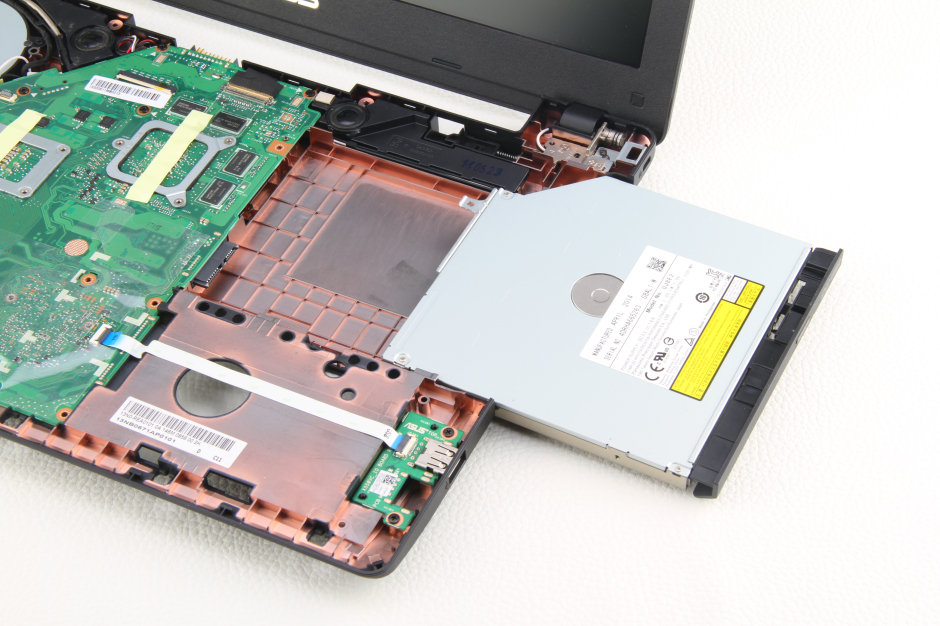
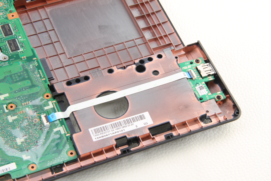
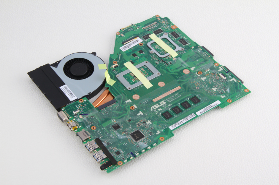
Under the palm rest, you can access the motherboard, DVD drive, speakers, wireless card, USB board, and cooling fan.
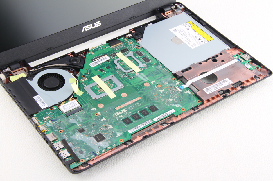
Remove the screw securing the DVD drive.
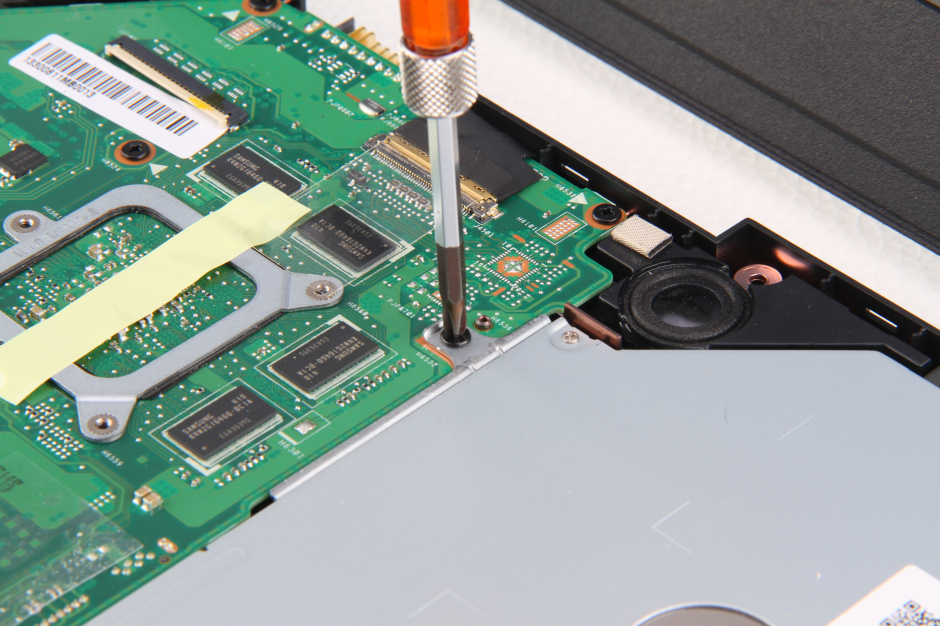
Pull out the DVD drive.
Disconnect two antennas and remove the screw securing the wireless card.
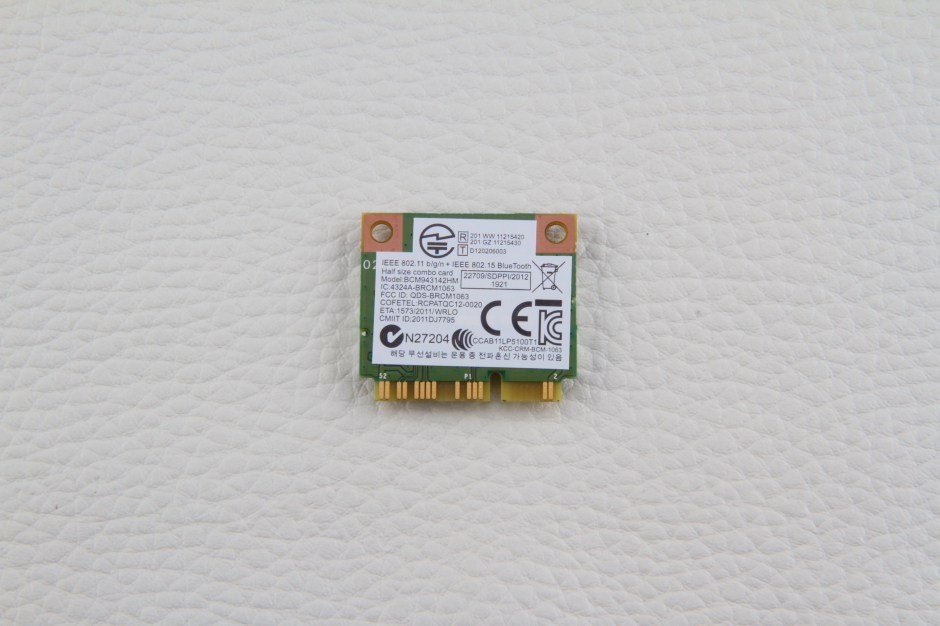
Remove the wireless network card from the slot.
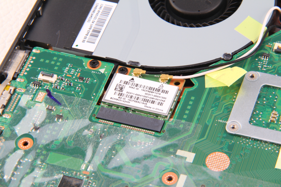
Wireless card
The USB board is connected to the motherboard via a cable.
Disconnect this cable.
Remove the five screws securing the motherboard.
Disconnect the LCD cable.
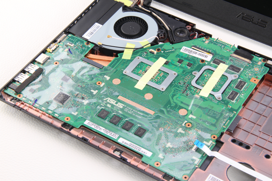
Lift the motherboard from one side with your hand and wiggle it until it completely separates from the laptop.
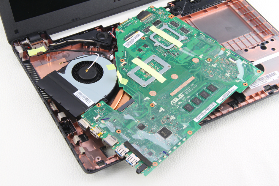
Disconnect all cables connected to the motherboard.
The motherboard has been removed.
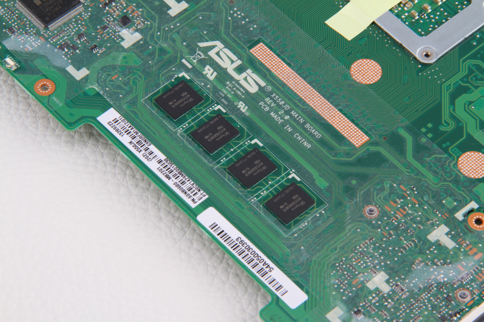
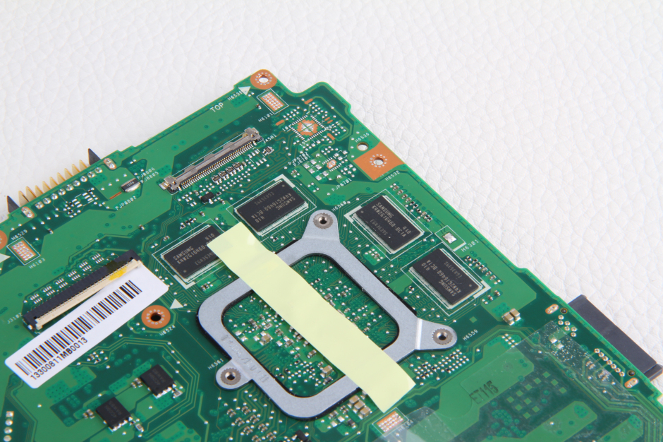
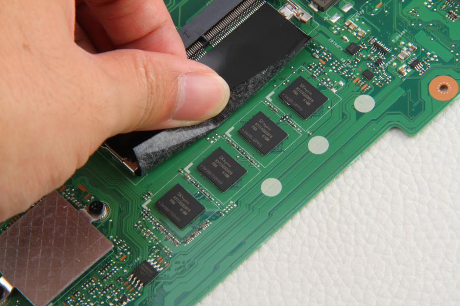
On the other side of the motherboard, four memory chips are also soldered.
Four Samsung video memory chips
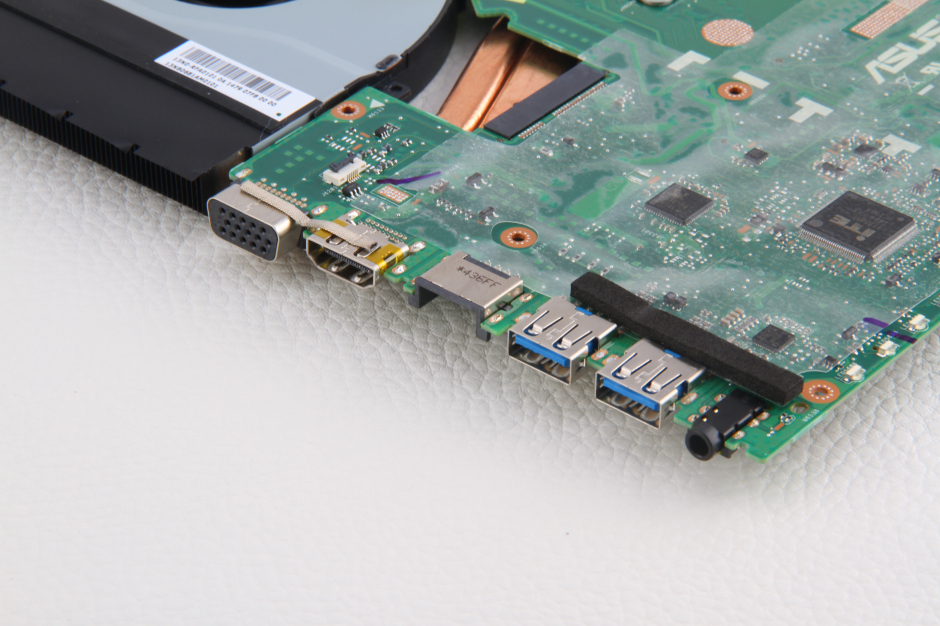
Ports
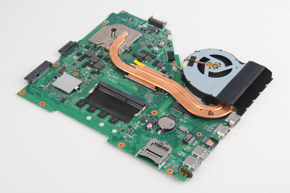
Motherboard
Four built-in SK Hynix memory chips
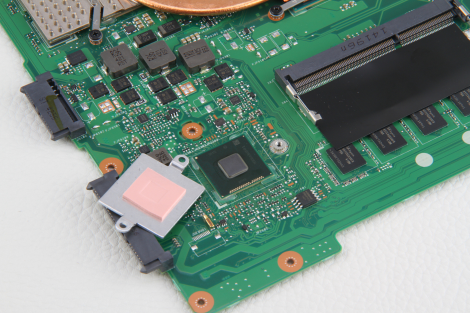
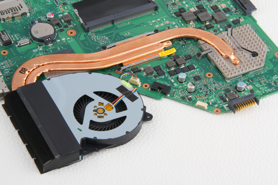
The south bridge is covered by the heat sink.
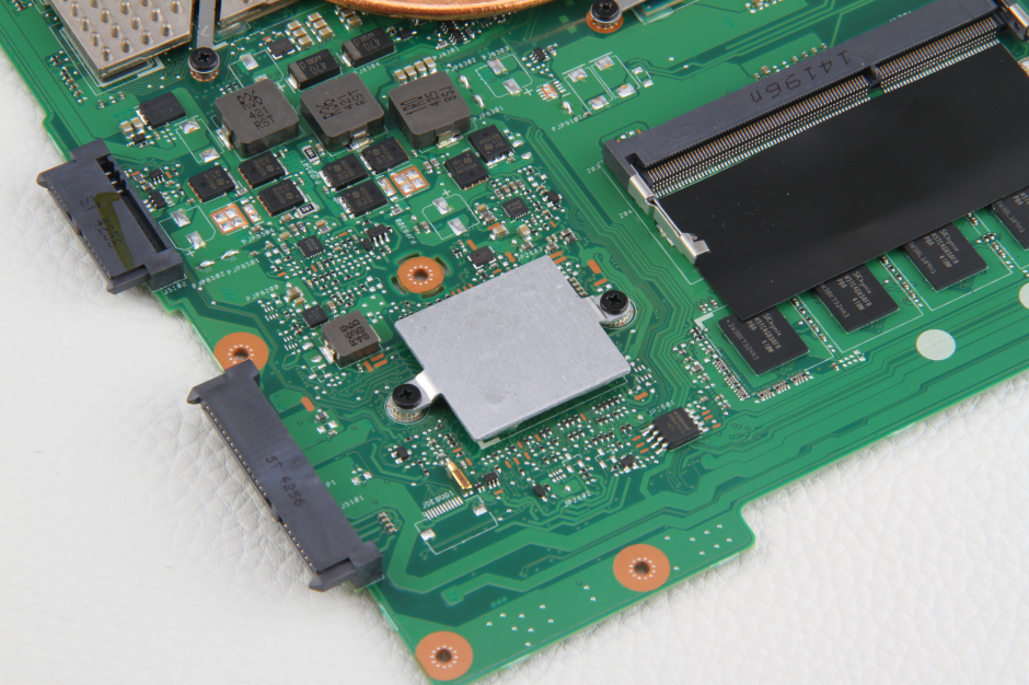
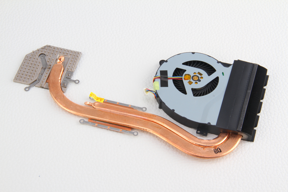
The heat sink has been removed.
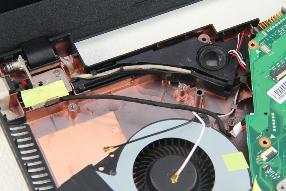
Remove the seven screws securing the heat sink and disconnect the cooling fan cable from the motherboard.
The heat sink and cooling fan have been removed.
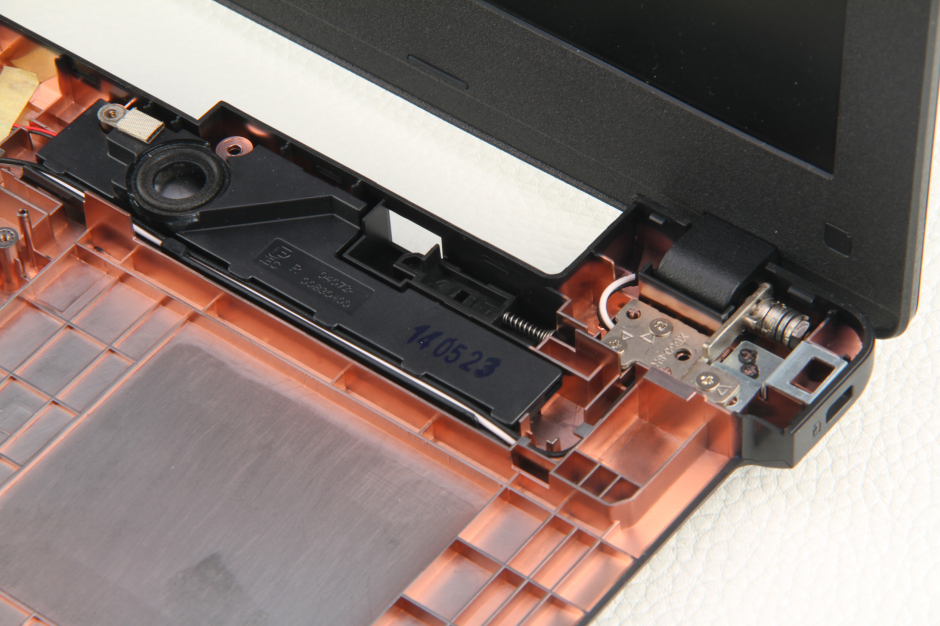
Right speaker and LCD hinge
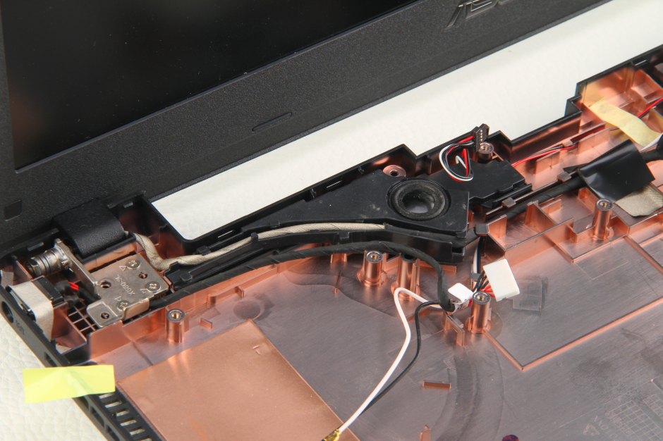
Left speaker
Asus A550JK internal parts
Hi! This is a nice tutorial and really helpful for an R510JK as well, since it’s the same layout.
I’ve replaced the optical drive with an SSD caddy. Unfortunately, I couldn’t remove the face plate/bezel of the UJ8E2 in order to attach it to the caddy. Have you disassembled the face plate of the optical drive as well? Could you post some advice/pics on how to get it done?
Thanks in advance.
Awesome manuals, David. Thank you so much for providing all these. This one is also good for X550L/N, too. I have had to replace the keyboard due to a couple of key failures. There were no spills or anything; it was just dodgy, I guess. I am looking at replacing the HD with an SSD and then placing the HD in a caddy, as Sprach has done above.
Sprach, did you just copy the recovery partition onto the external and then copy it onto your SSD? How do you start the computer if the SSD is empty? I want the original recovery partition. How to do that? Where did you get your caddy? Any advice before I do this? Thanks 🙂
Hi!
I would like to ask where the warranty seals are located. I have 3 3-year warranty, and I don’t want to lose it. Could you please let me know?