In this guide, I will explain how to disassemble the Dell Latitude E7240 laptop to remove and replace its components, including the SSD, keyboard, palm rest, memory module, wireless network card, bottom cover, heat sink, cooling fan, and motherboard.
Join us on the social network! Follow us on Facebook for all the latest repair news.
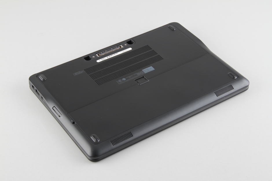
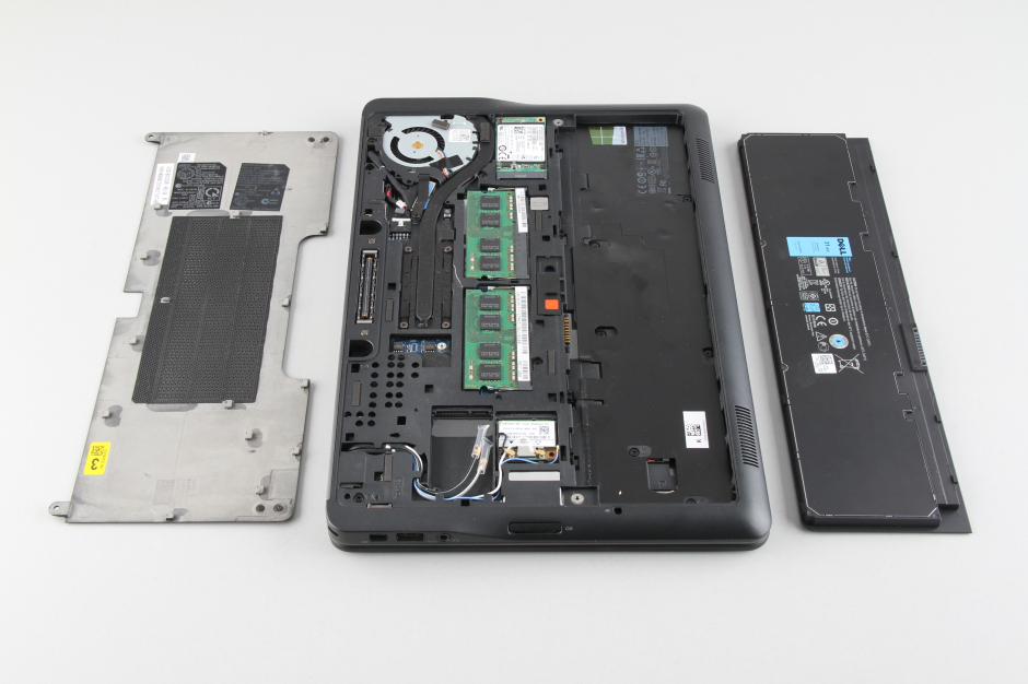
Unlock and remove the battery.
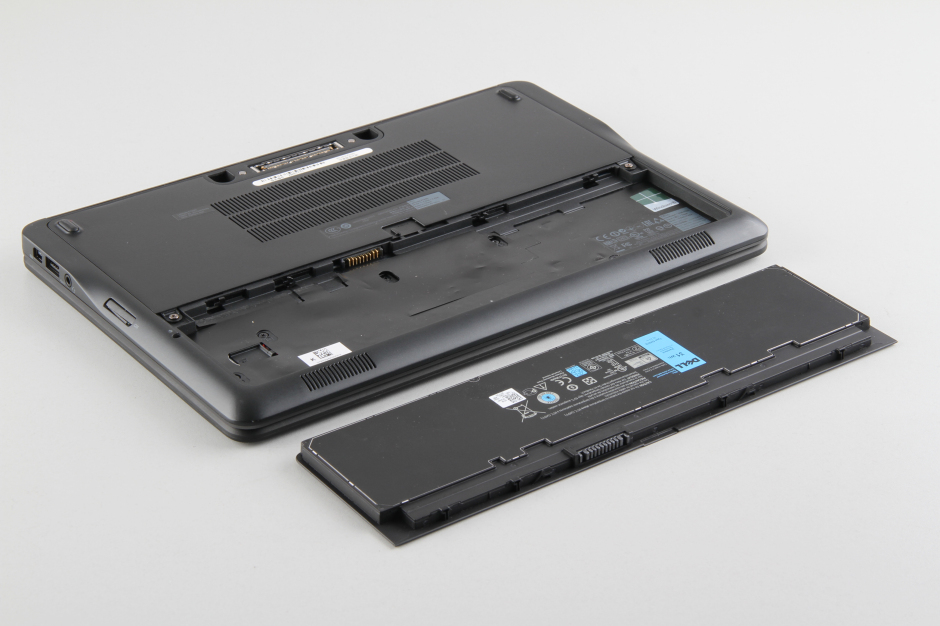
The Dell Latitude E7240 Touch features an 11.1V, 31Wh Li-polymer battery. The Dell part number is GVD76.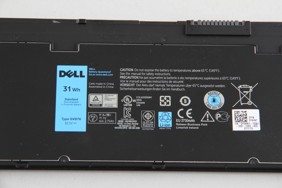
Remove the two screws securing the service cover.
Pry up and remove the service cover.
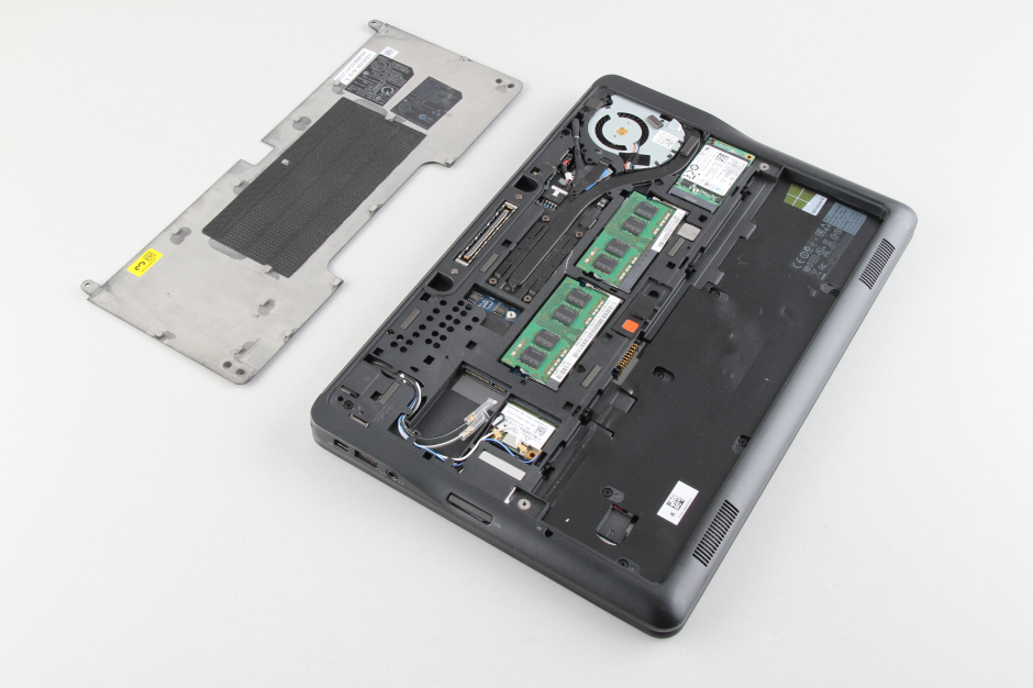
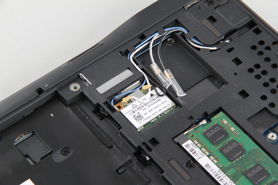
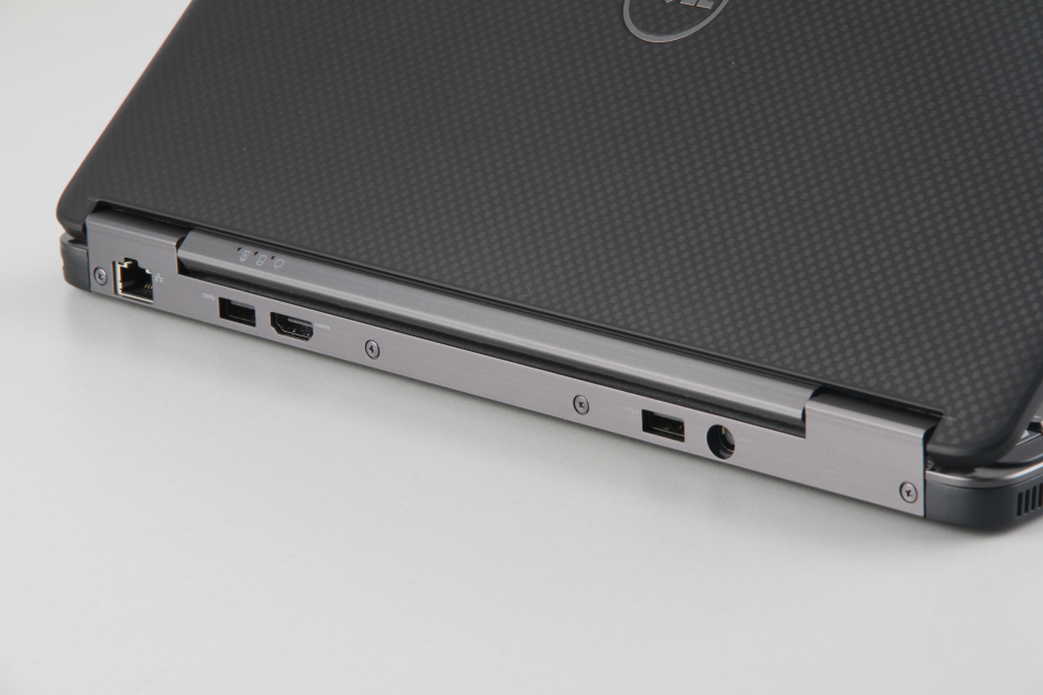
Under the cover, you can access the hard drive, RAM, SSD, wireless card, heat sink, and cooling fan.
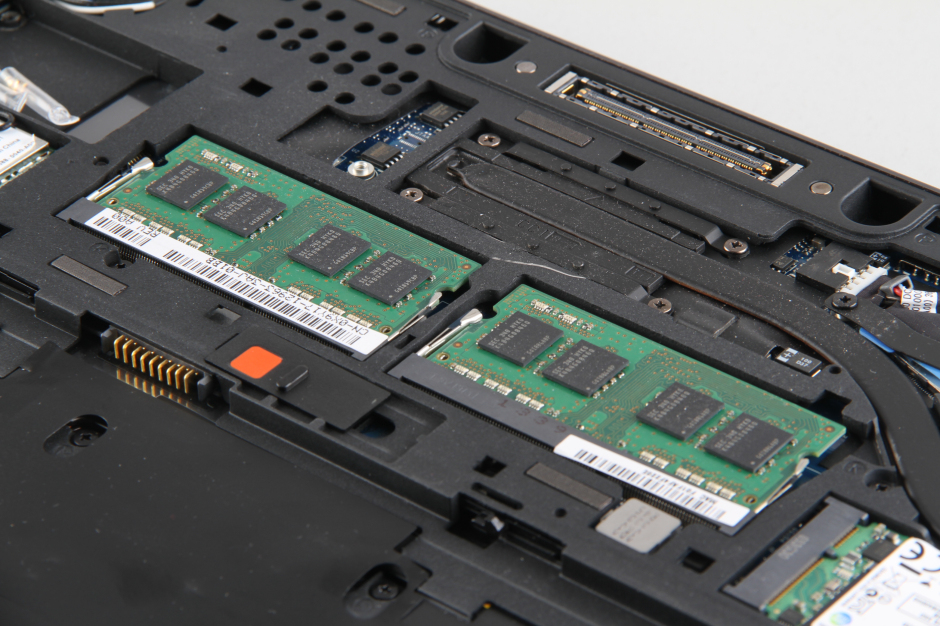
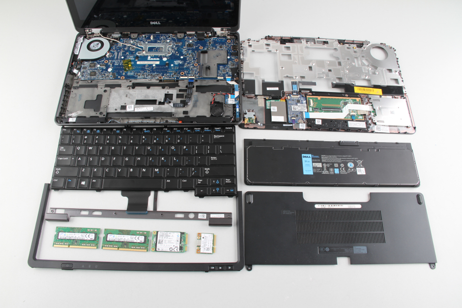
This laptop has two memory slots, each with 4GB of memory installed, for a total of 8GB of memory.
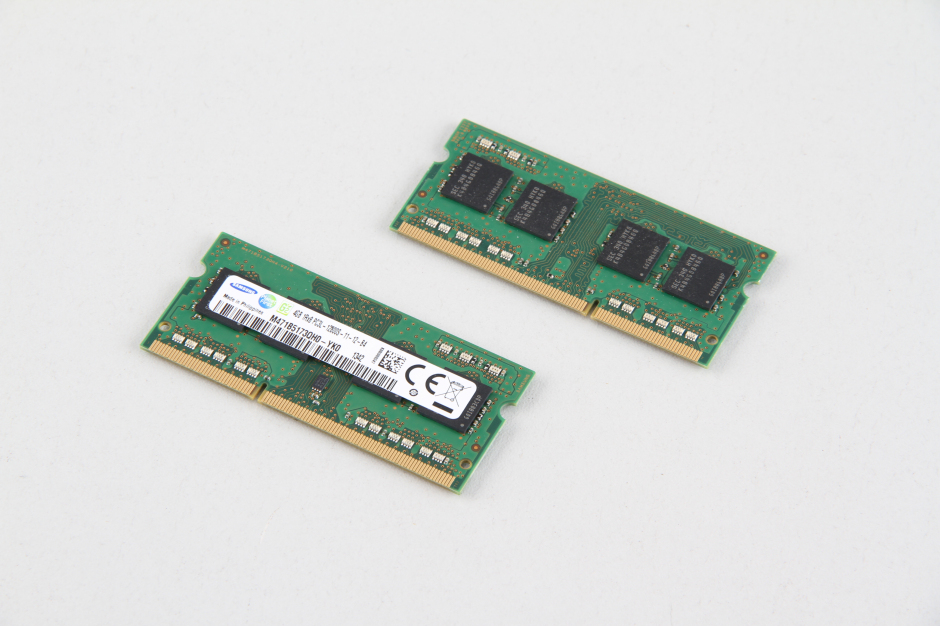
Two Samsung 4GB PC3L-12800S memory modules.
Remove the screw securing the SSD and carefully remove it from its slot.
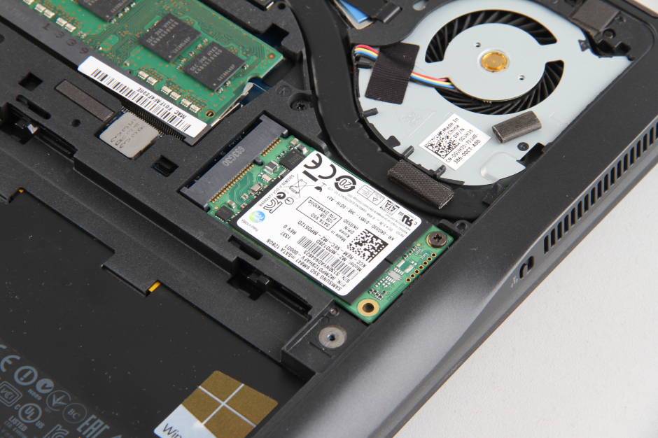
The SSD will automatically pop out after removing the screws.
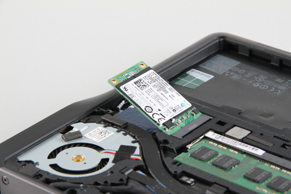
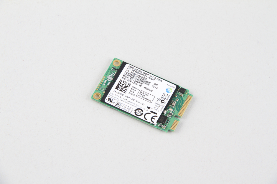
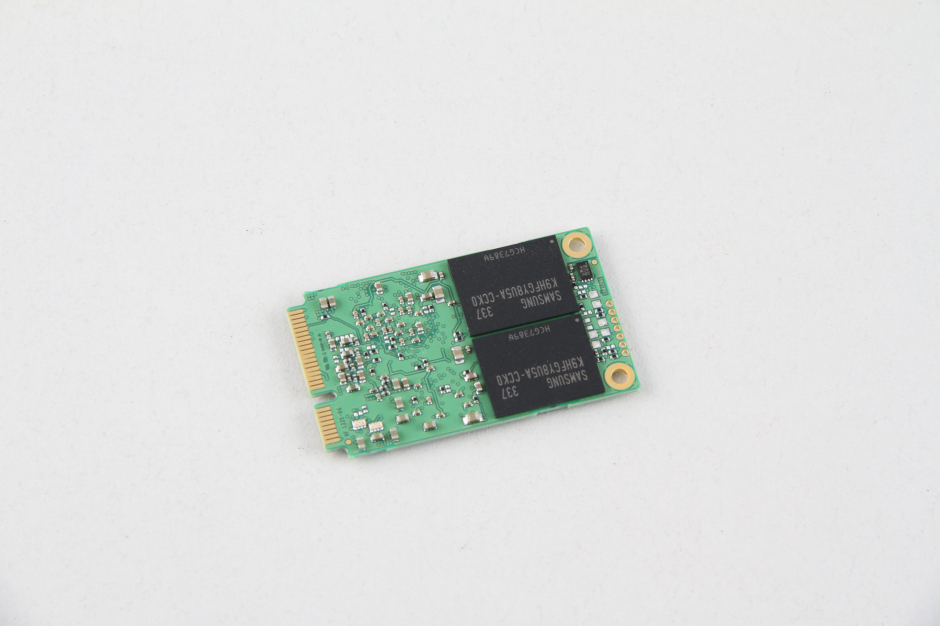
This Dell Latitude E7240 Touch features a Samsung 128GB mSATA SSD.
Remove the screw securing the wireless card.
Disconnect two wireless antenna cables.
Remove all screws from the bottom case. Turn over the laptop.
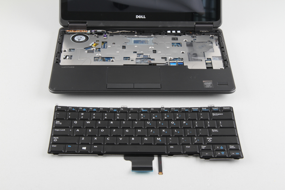
Remove the keyboard bezel.
Remove all screws securing the keyboard.
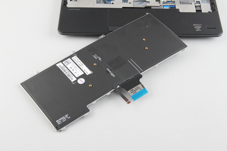
Lift up the keyboard. Disconnect the keyboard cable and backlit cable, and you can remove the keyboard.
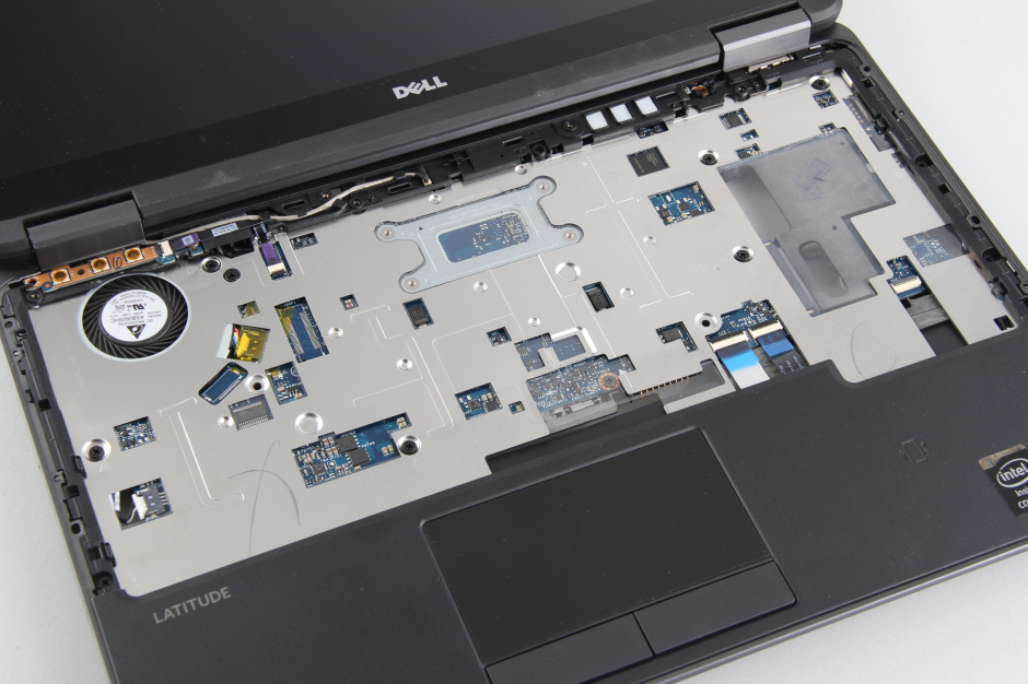
Remove all screws securing the palm rest.
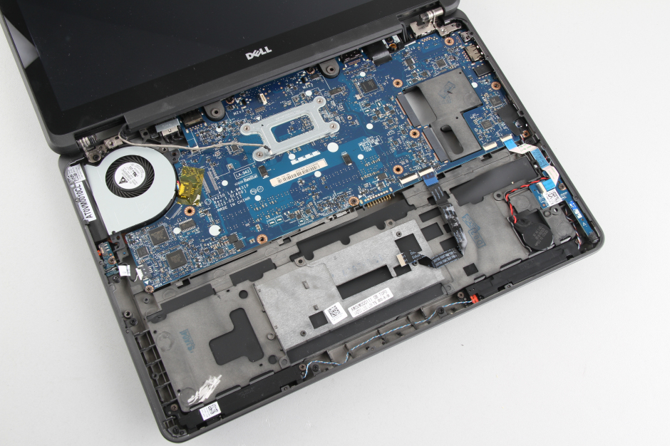
Disconnect four visible cables from the motherboard.
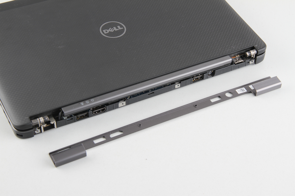
Remove the four screws on the rear of the laptop.
Remove the LCD hinge cover.
Insert a prying tool between the palm rest and the bottom cover, and slide the prying tool to detach the palm rest from the bottom cover.
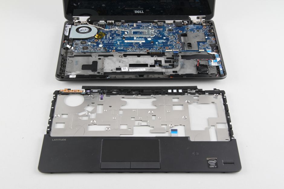
The back of the palm rest.
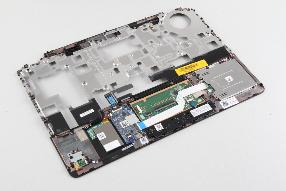
When the palm rest is removed, you can access the CMOS battery, speakers, and motherboard.
Close-up of all removed parts.
Where can I locate the BIOS chip or IC on the motherboard?
Just remove the BIOS battery, and your BIOS password will clear automatically.
I want to clear the BIOS password on the motherboard (Latitude E7240).
You should update the wording of the service cover removal instructions. The cover does not snap off by prying up. This breaks some of the catches. It should say to slide the cover toward the battery compartment, and it will then lift off easily.
Where is the SSD actually located on this laptop?