
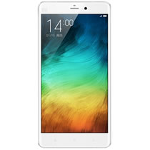
On February 24, Xiaomi held a press conference at the China National Convention Center in Beijing and officially released the Xiaomi Mi 5.
The Xiaomi Mi 5 features a 5.15-inch 1080p display, a Qualcomm Snapdragon 820 processor, and 3 GB and 4 GB of RAM, along with 32 GB, 64 GB, and 128 GB of storage. It features a 4MP front camera and a 16MP rear camera, along with a 3000mAh battery.
The 3GB 32GB variant is priced at CNY 1,999, the 3GB 64GB variant is priced at CNY 2,299, and the 4GB 128GB variant is priced at CNY 2,699.
Want to be the first to see inside the latest gadgets? Follow us on Facebook for the latest news from MyFixGuide.com.
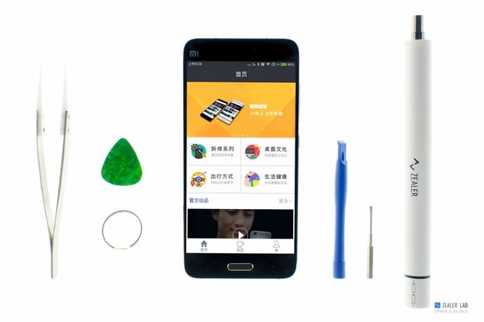
Tools needed: Screwdriver, tweezers, crowbar, suction cup, guitar pick
Remove the SIM card tray with an E-ject pin.
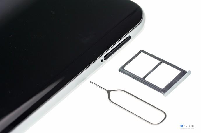
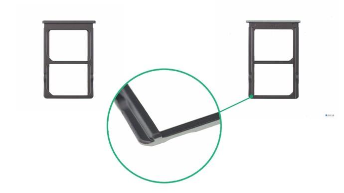
Card tray design: dual Nano-SIM card
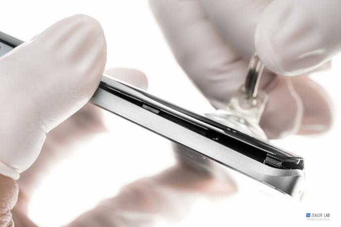
The back cover of the Xiaomi 5 is made of glass and secured to the body with clips.
Gently pry up the edge of the back cover using a suction cup, then insert your finger between the cover and the body to remove it.
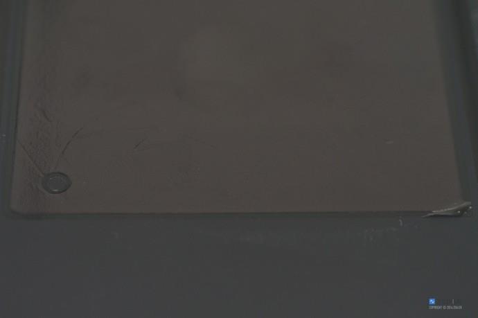
There is a layer of graphite thermal film on the back cover.
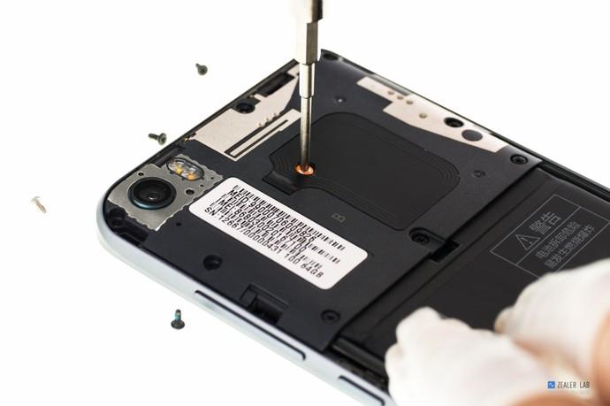
Remove the nine screws securing the antenna bracket.
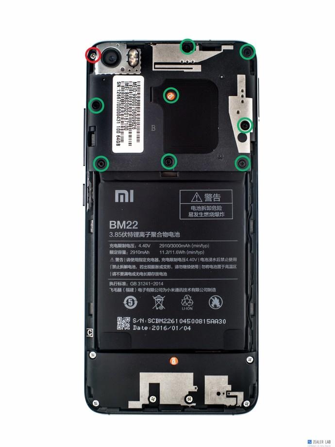
There is a screw covered with a warranty sticker. If you damage it, you will void the warranty.
Remove the antenna bracket.
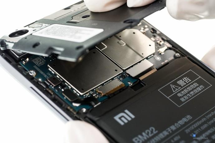
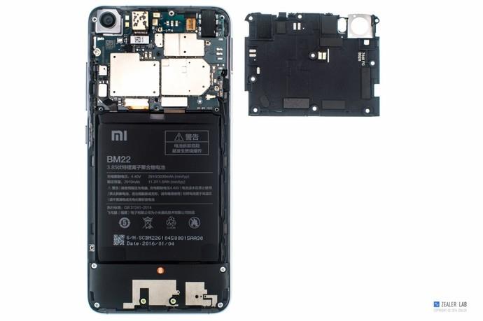
After removing the antenna bracket, you can access the motherboard and camera.
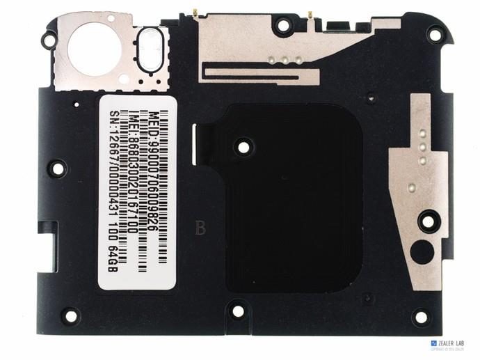
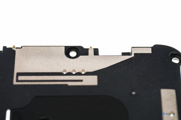
GPS antenna (top) and Wi-Fi / BT antennas (right)
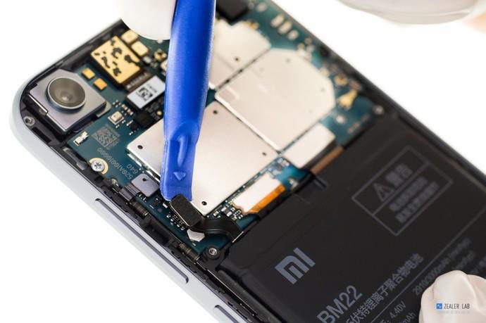
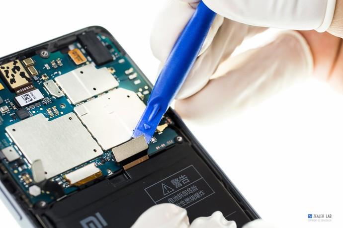
Disconnect the battery connector from the motherboard.
Disconnect the sub-board cable, LCD cable, side button cable, and distance sensor cable.
Disconnect the RF antenna.
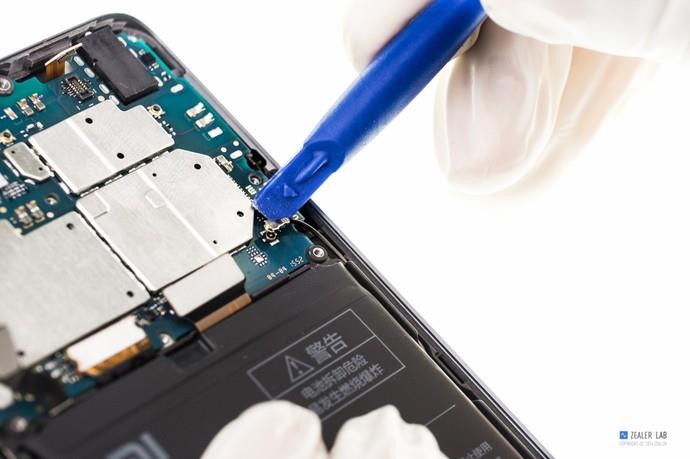
Remove the screws securing the motherboard.
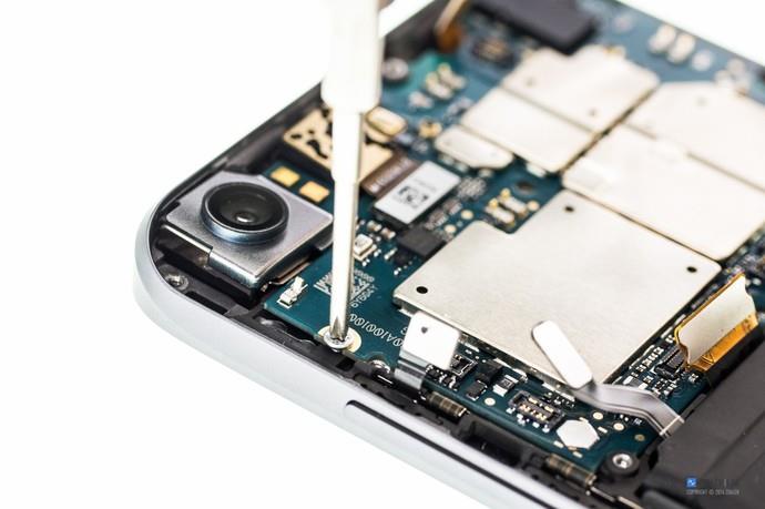
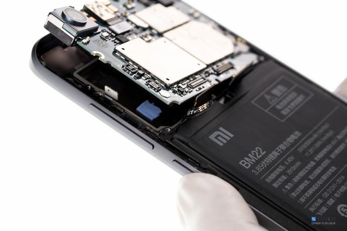
Lift and remove the motherboard.
Remove the front camera.
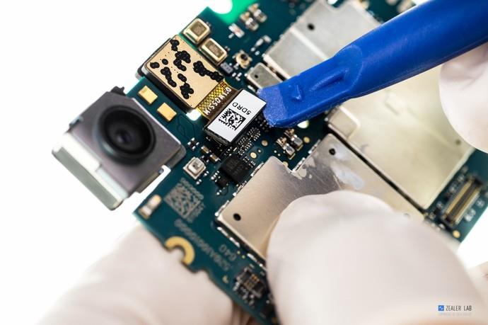
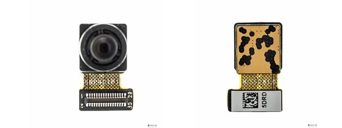
Close-up of the front camera module.
4MP, f/2.0 aperture, 80 degrees wide-angle
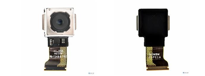
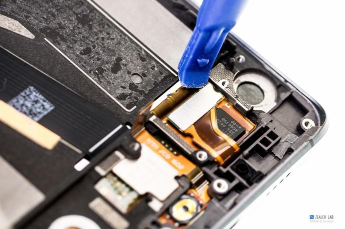
Disconnect the rear camera connector from the motherboard.
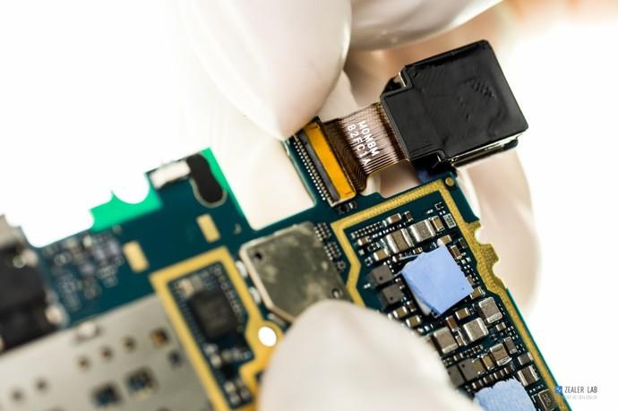
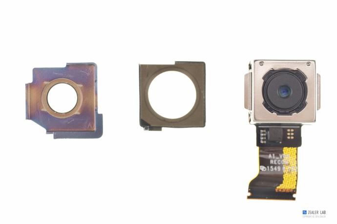
Close-up of the rear camera module.
16MP, f/2.0 aperture, support axis optical image stabilization, phase focusing
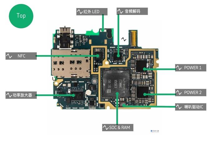
SOC: Qualcomm Snapdragon 820(MSM8996), 14nm FinFET, 64-bit Kryo 4 Core
GPU: Adreno 530 GPU 624MHz
RAM: SEC Samsung 543 K3RG4G4 OMMMGCJ, 3GB LPDDR4 1866 MHz two-channel
POWER Management IC: Qualcomm PMI8994
POWER Management IC: Qualcomm PM8996
SPEAKER DRIVER IC: NXP TFA9890A
NFC: NXP 66T17
AUDIO DECODER IC: Qualcomm WCD9335
POWER AMPLIFIER MODULE: SKYWORKS 77646-51 Multimode Multiband Power Amplifier Module
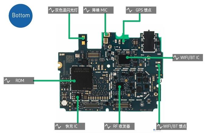
ROM: TOSHIBA THGLF2G9J8LBATR, UFS 2.0, 64GB
Quick Charge IC: Qualcomm SMB1351, Quick Charge 3.0
Wi-Fi/BT IC: Qualcomm QCA6164A
RF Transceivers: Qualcomm WTR3925
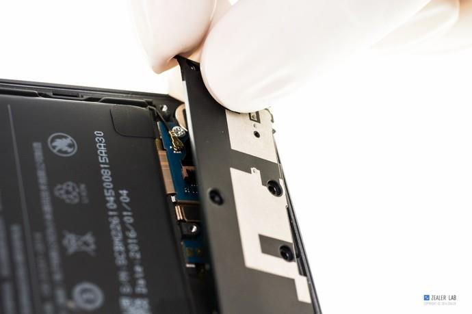
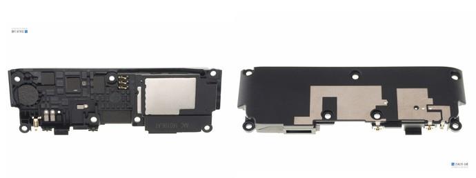
Remove the seven screws securing the speaker module.
Remove the speaker module from the phone body.
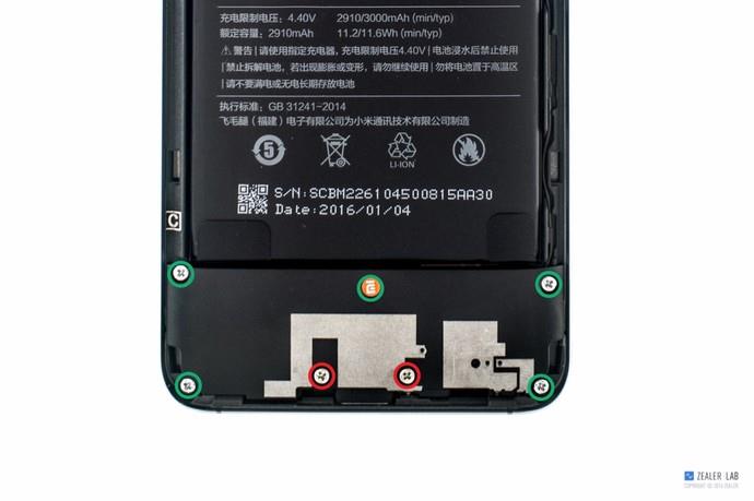
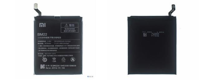
Remove the battery from the phone.
Charging voltage: 4.40V 3000mAh
Rated capacity: 2910mAh 11.2/11.6Wh
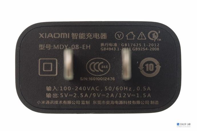
Xiaomi Mi 5 charger
Input: 100 – 240VAC, 50/60Hz, 05A
Output: 5V 2.5A/9V 2A/12V 1.5A
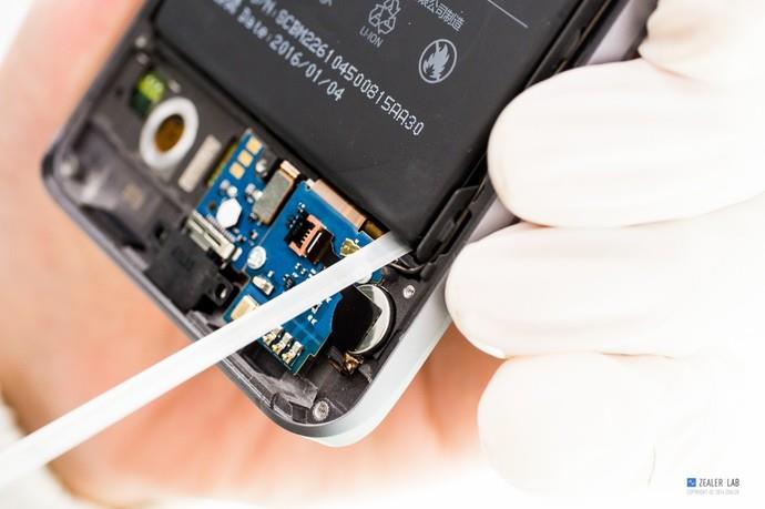
Remove the two screws securing the sub-board.
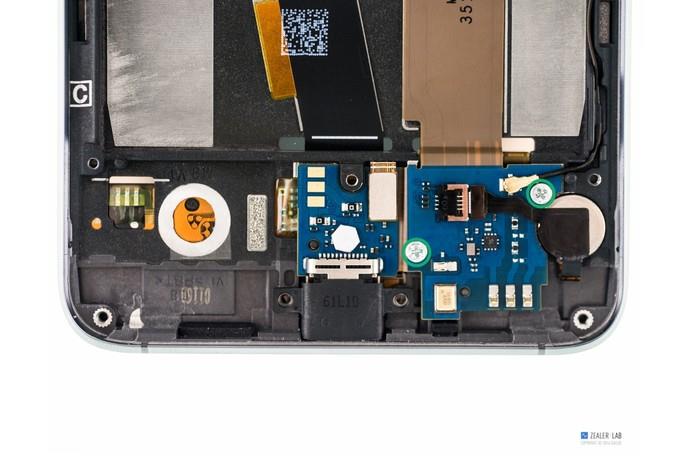
Disconnect the vibrator from the board.
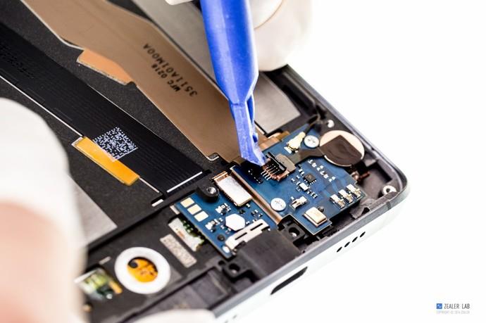
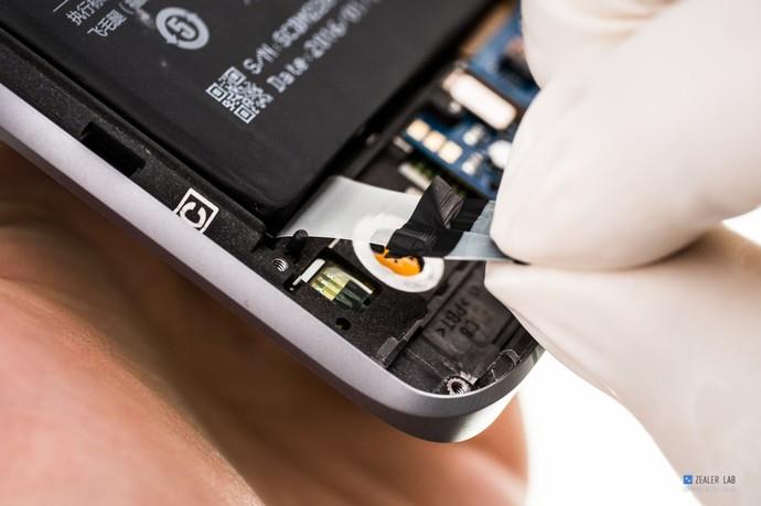
Disconnect the fingerprint home key.
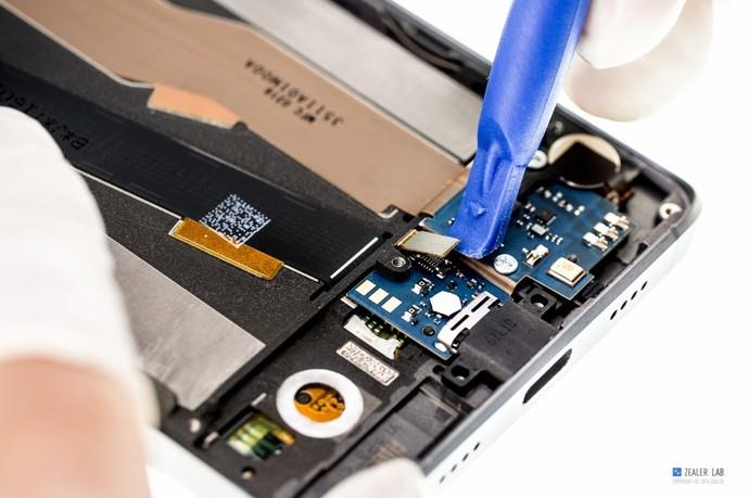
Disconnect the RF antenna.
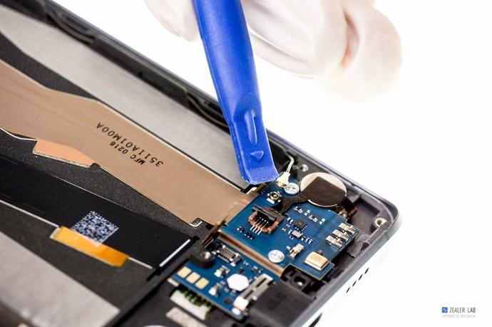
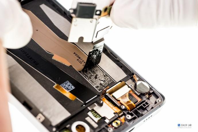
The sub-board cable is secured to the body with double-sided adhesive tape.
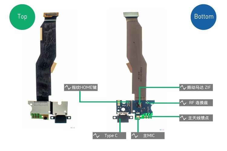
The vibrator, main MIC, Type-C port, FR connect socket, and fingerprint home key are integrated into the sub-board.
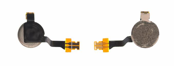
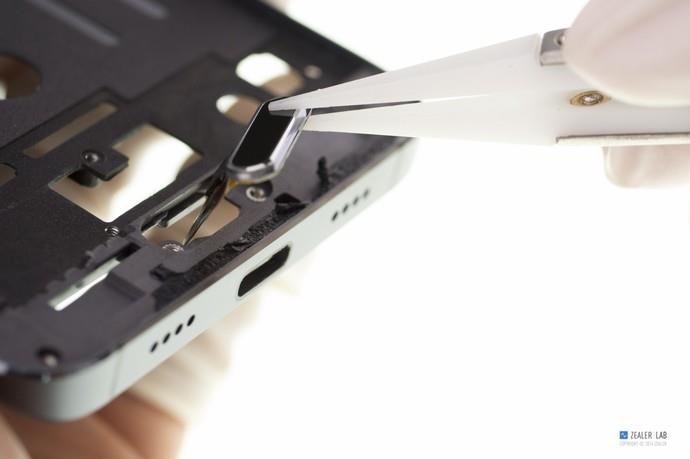
Remove the vibrator with tweezers.
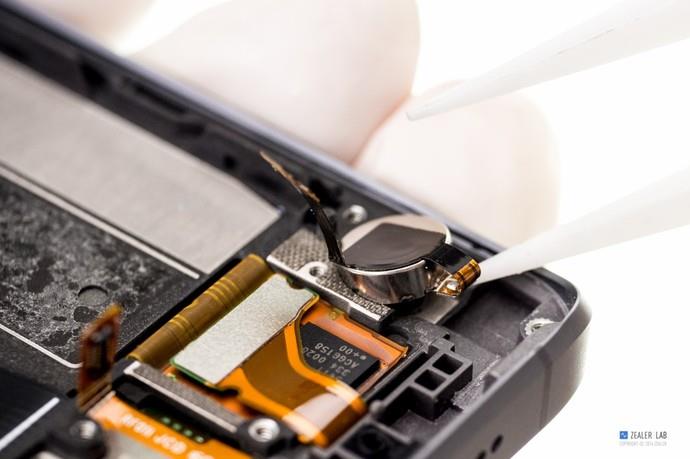
The vibration motor, the model 0825, uses the ZIF connector.
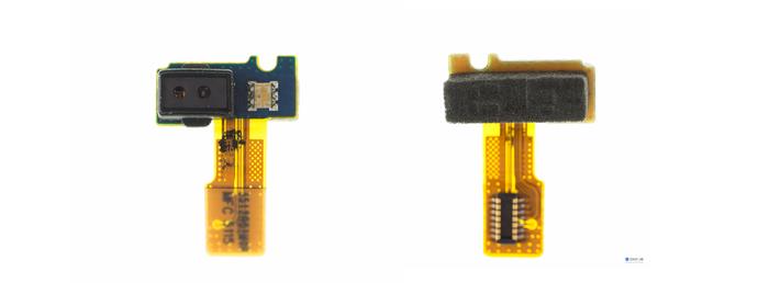
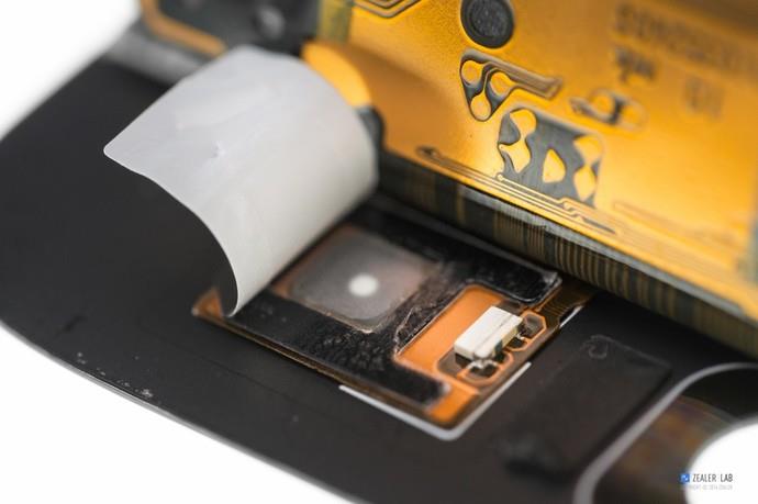
Remove the light distance sensor with tweezers.
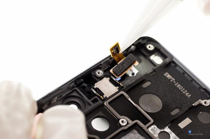
Close-up of the light distance sensor.
Remove the telephone receiver with tweezers. It is secured with foam rubber.
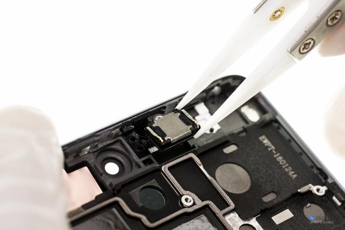
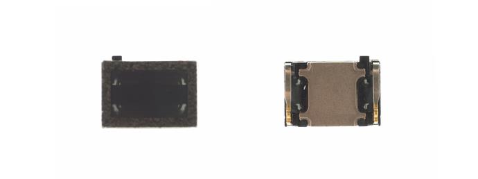
Telephone receiver
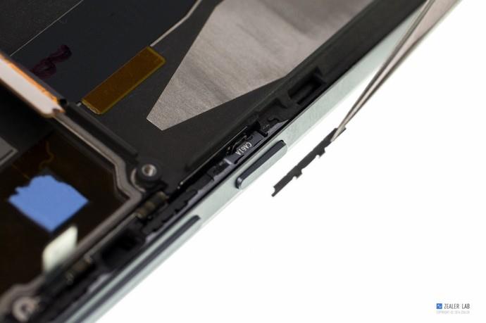
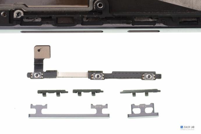
Remove the side button.
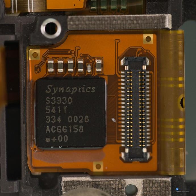
Disconnect the touch BTB.
The touch IC comes from Synaptics.
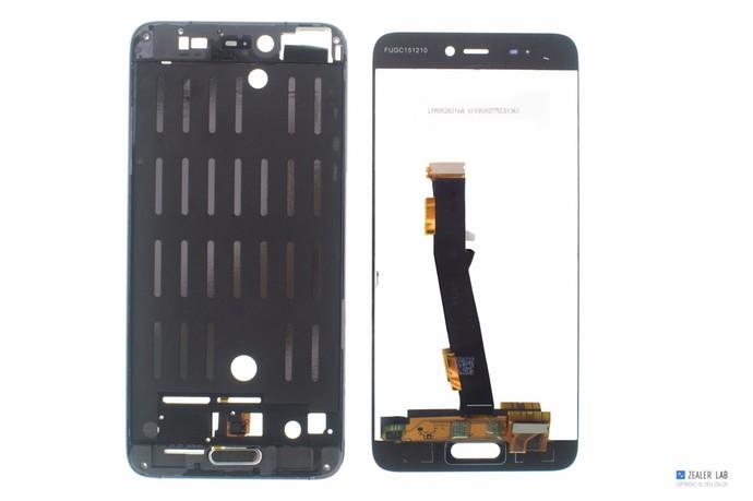
Heat the front of the screen with a hot gun for about 5 minutes.
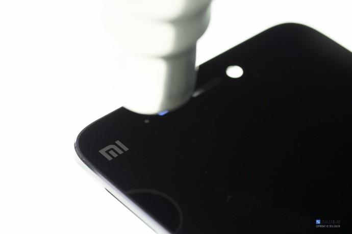
Close-up of the display assembly.
Touch button and button light
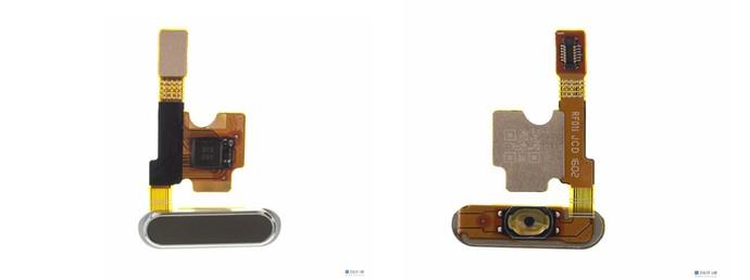
Remove the fingerprint recognition module with tweezers.
The width of the fingerprint recognition module is only 4.68mm.
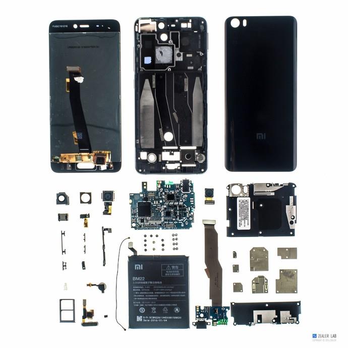
Xiaomi Mi 5 internal parts

I need a power IC for MI5. Could you please advise where I can find the IC and what the price is?
Did you find it? Please reply. Thank you.
The best photos so far, very good job.
This is the first time I have seen how to remove the side button, as I need to replace it. I also need to know if it is necessary to remove the battery and the motherboard.
Any detailed help or tips are welcome
Thank you,
Zarb
I want to replace the battery. I know every step, but I need help knowing exactly which screwdrivers are required.
I want to replace the battery terminals on the board. Please show me the jumper ways.
Is the main camera connector somehow related to the phone’s audio sound? After replacing the telephone receiver, my sound disappeared. I suggest that I caused bad contact with the mainboard somewhere during assembly. The headphone sound works perfectly, but the audio is gone. The speaker works perfectly on another phone. I figured out it was due to some bad contact in the area of the main camera. Beforehand, when trying to play a sound, the phone would directly restart. After pressing the button in the area of the main camera, the phone stopped restarting. But the sound is gone.
Is it repairable? Where is the mainboard’s connector to the speaker’s cable?
Thank you!