Need Tools:
Phillips screwdriver
Plectrum
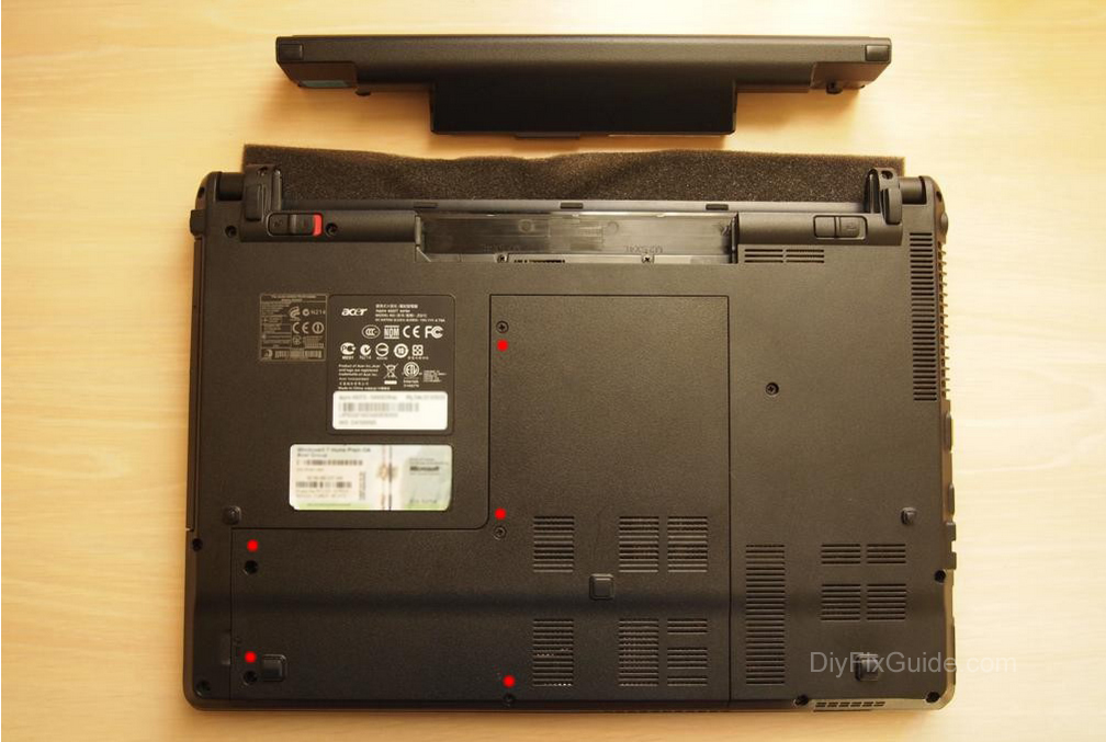
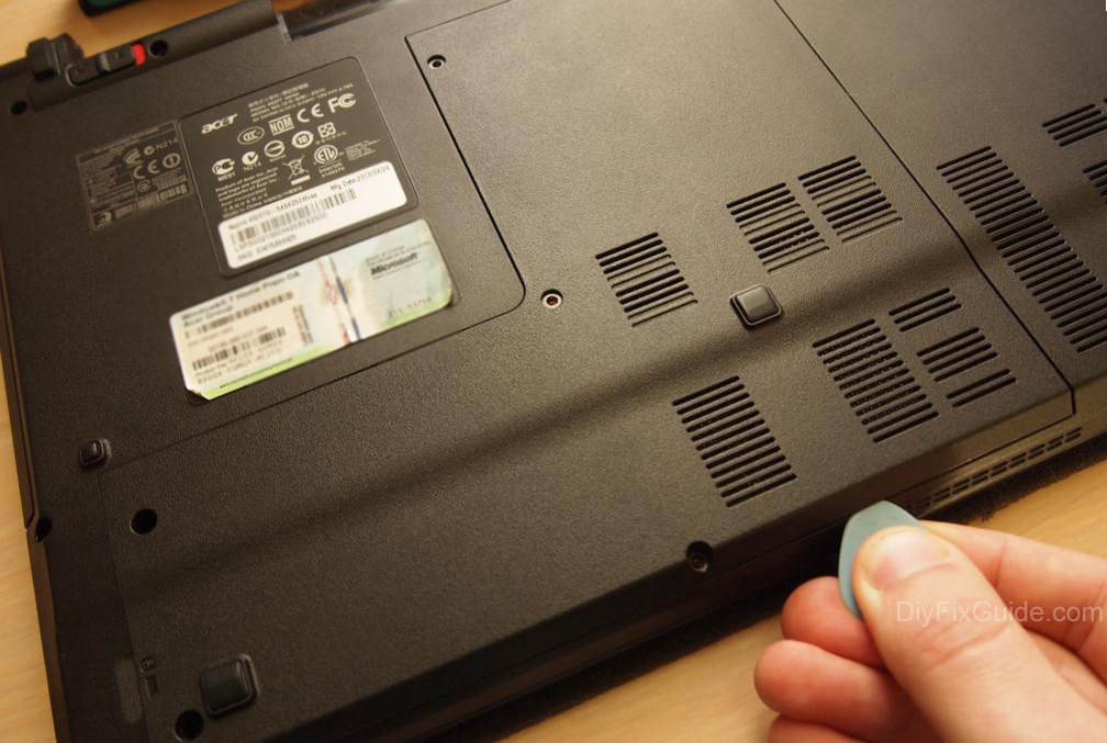
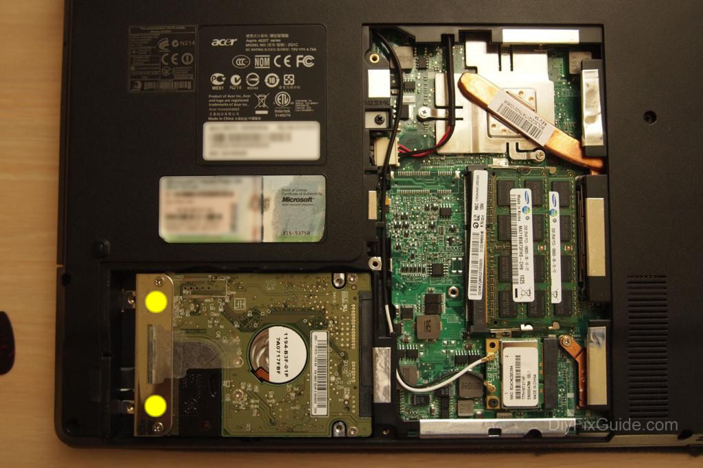
Step 1
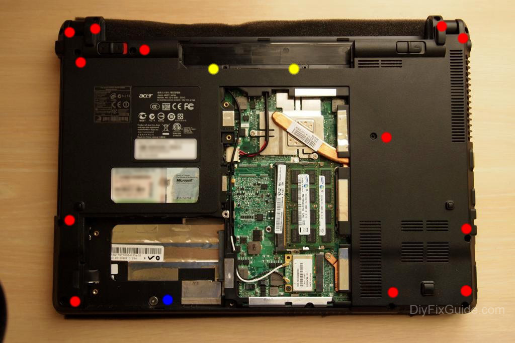
Removing the memory cover
The procedure is very simple. Unscrew the five screws, then use a plectrum to gently force the edges of the laptop to remove the cover.
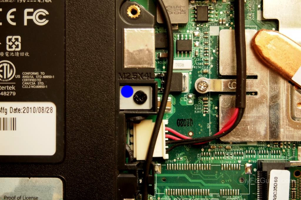
I recommend that you keep the screws in the same place where they were found to ensure that you don’t miss their location during reassembly. In my case, I have marked the different screws you will encounter with different colors.
Step 2
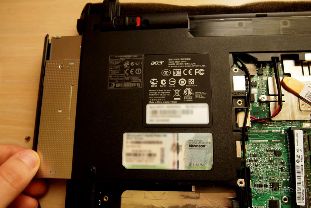
Removing the hard drive
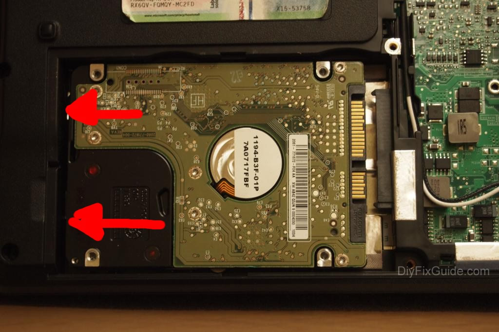
To replace the hard drive, you must unscrew the two screws that I have marked in the image below.
Once this is done, you can pull off the plastic tab on the metal piece.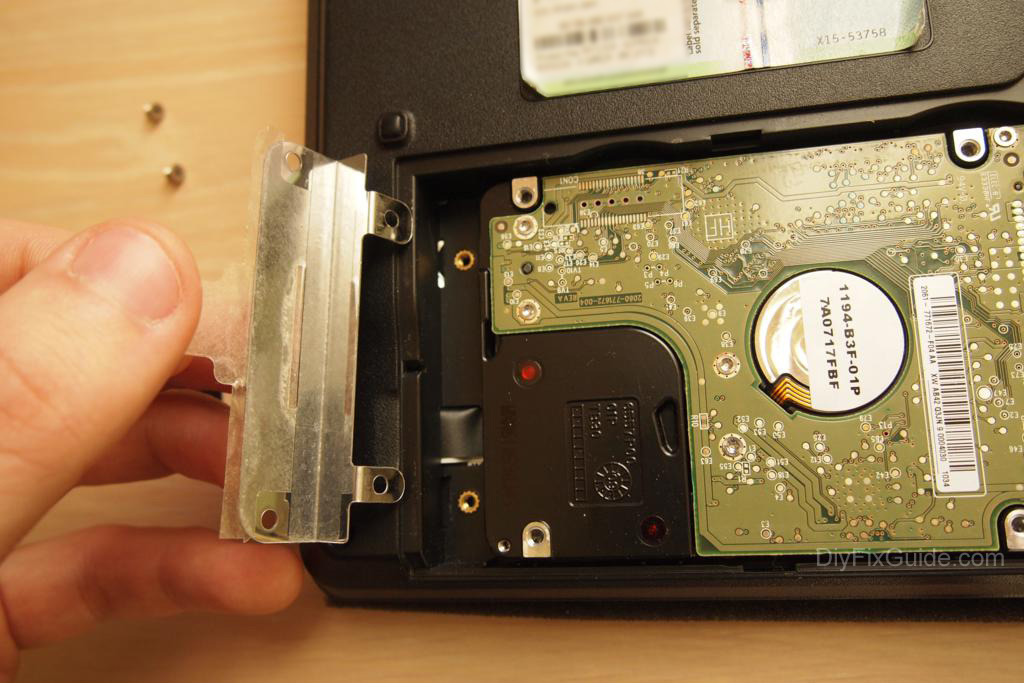
The hard drive will be free to come off after pushing it to the left (and disconnected from its SATA connector)
Step 3
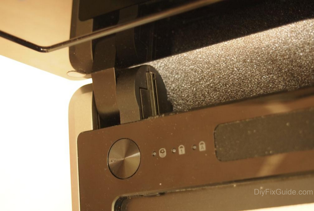
Removing the optical drive
Unscrew a screw and pull it out.
Step 4
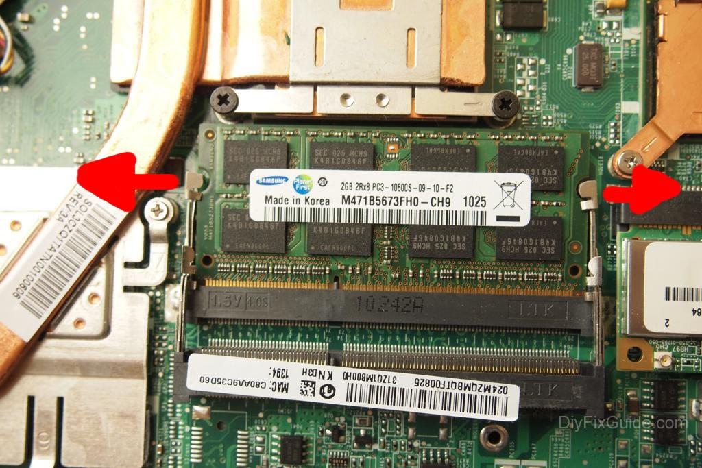
Removing the RAM
The memory module is held in place by two metal side rails. You must push them to the outside to ensure that the module can only be lifted if it is possible to remove it.
Step 5
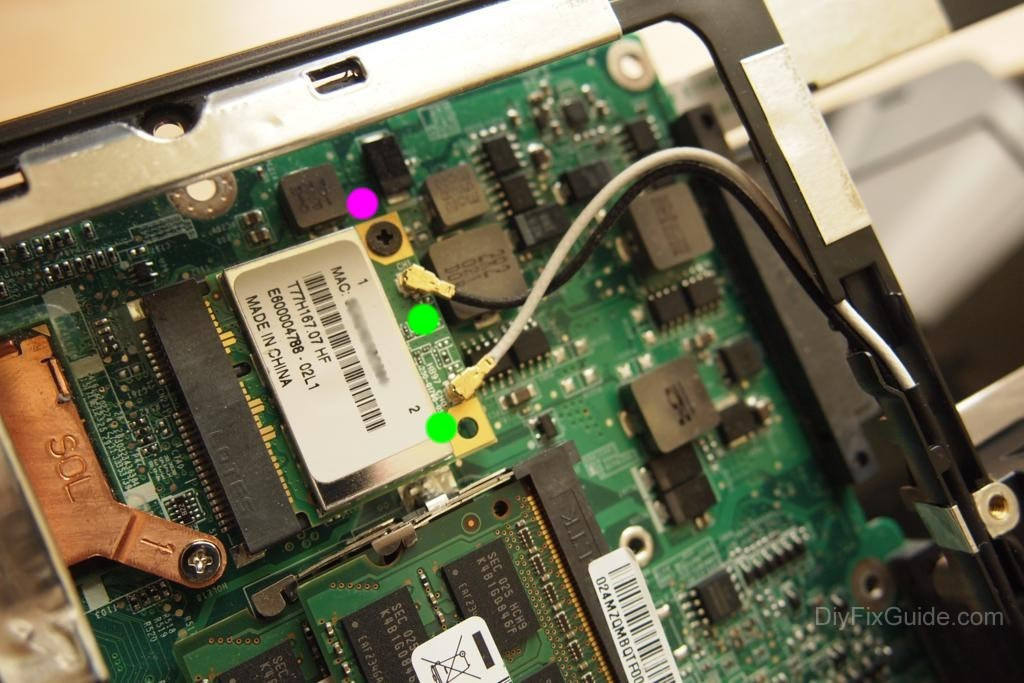
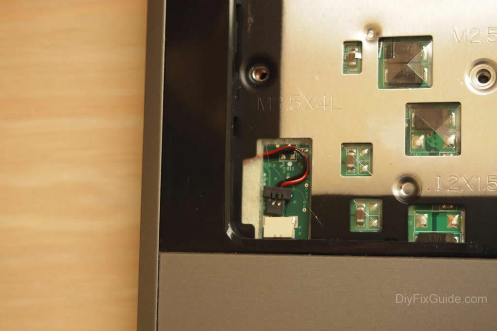
Removing the wireless card
The wireless card is located near the RAM module. To access it, you must unscrew a screw and remove both antennas.
Step 6
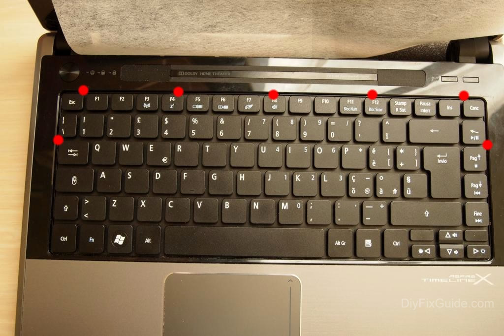
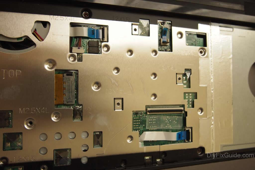
Removing the keyboard
Unscrew all the screws located under the laptop. As usual, I marked the different screws you will encounter with different colors.
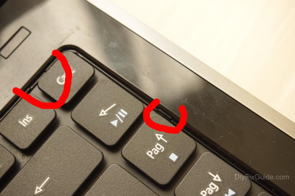
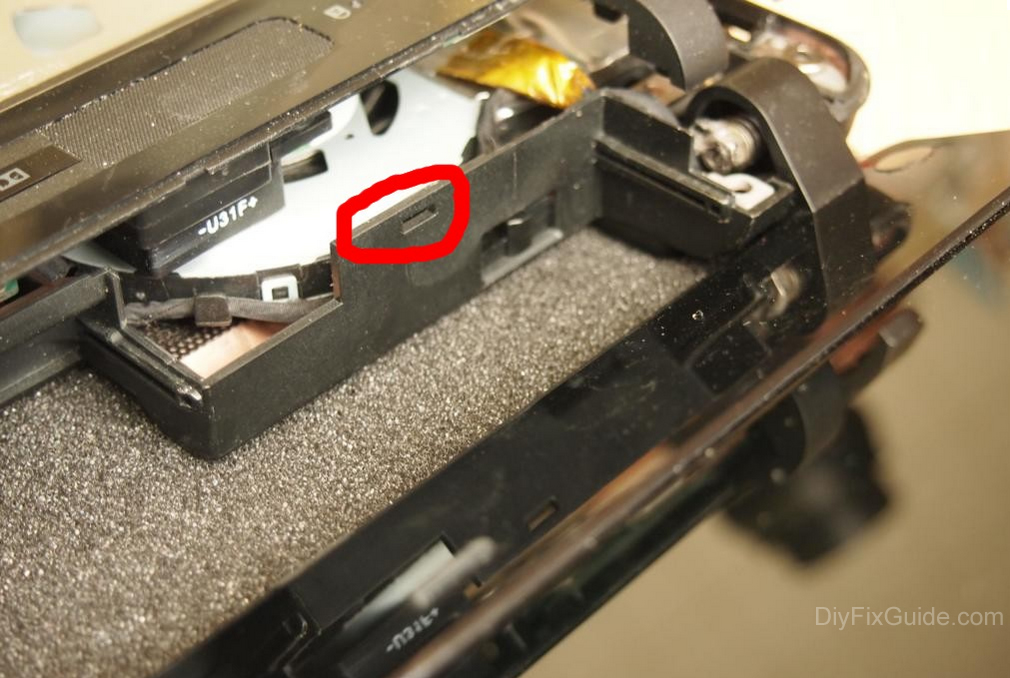
On the other hand, we have to remove the keyboard. You can see a small piece of plastic. They are still facing outwards to make sure the keyboard is unlocked. I have marked their locations in the image below.
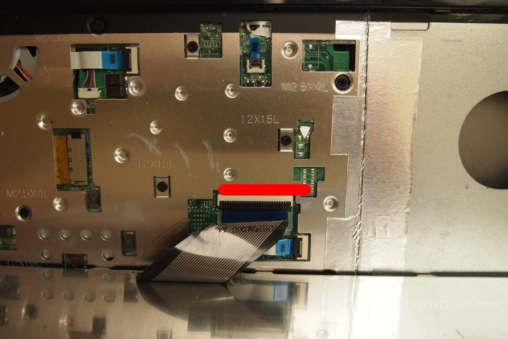
Warning: Do not crush the ribbon cable connected to the motherboard when you pull the keyboard towards you (it may damage the keyboard and motherboard connectors).
The black tie lever on the connector must be lifted to pull out the keyboard ribbon cable.
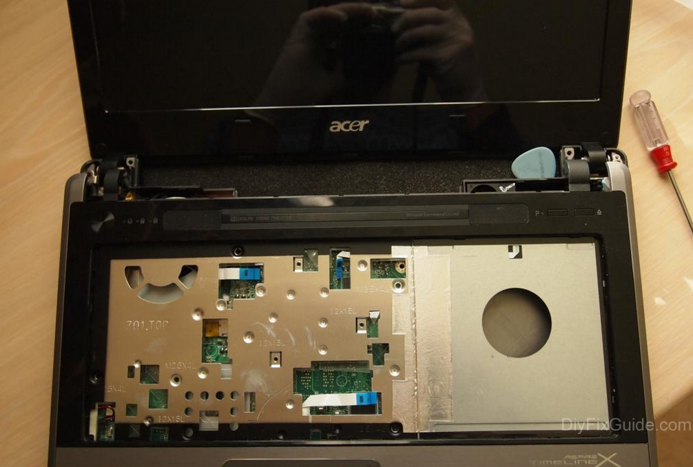
At this point, you must unscrew all other screws hidden by the keyboard. Also, you must disconnect all cables from the connectors.
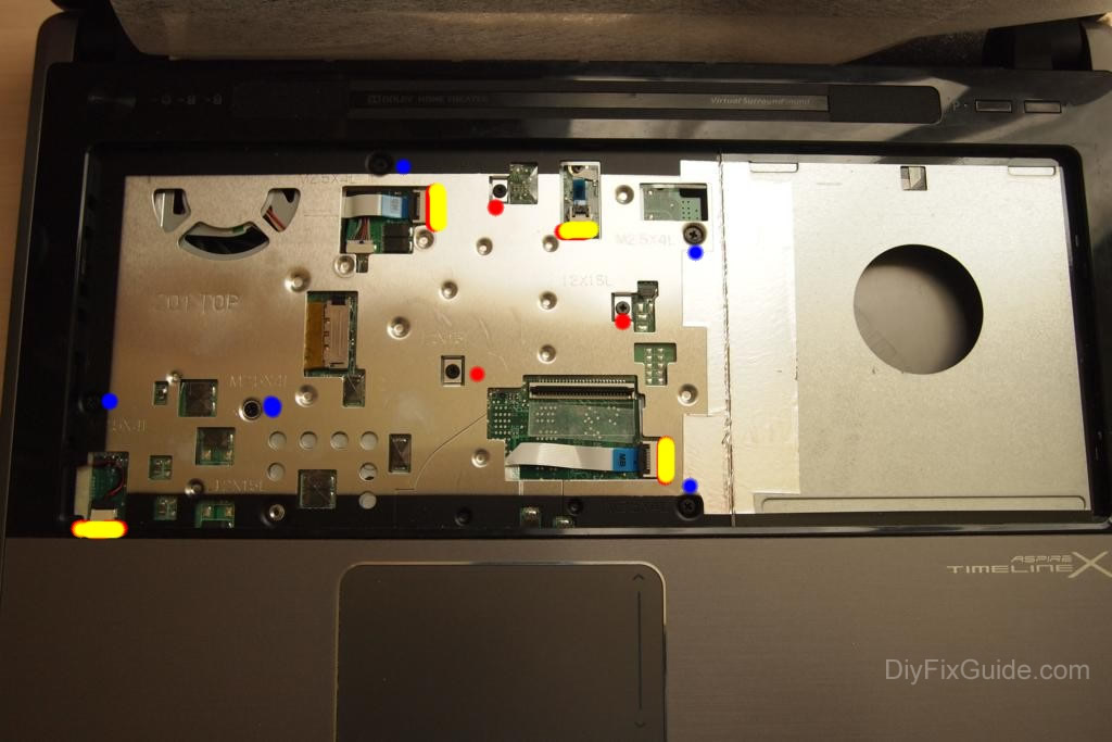
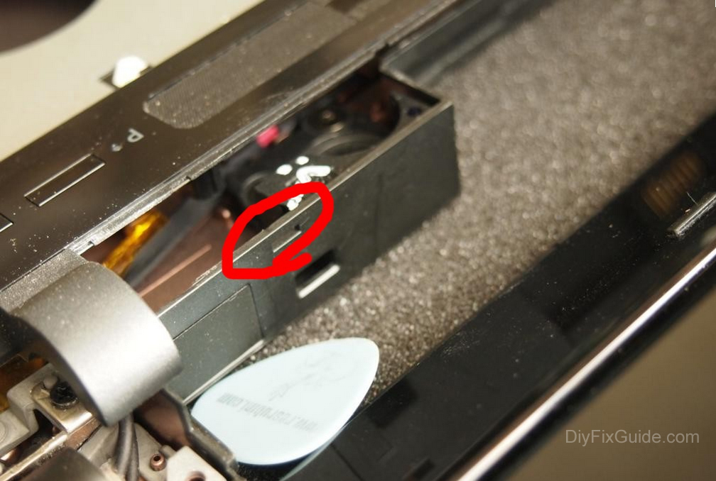
Special connectors for the free position to release the cables
This is a snap-on connector with the cable head already pulled out.
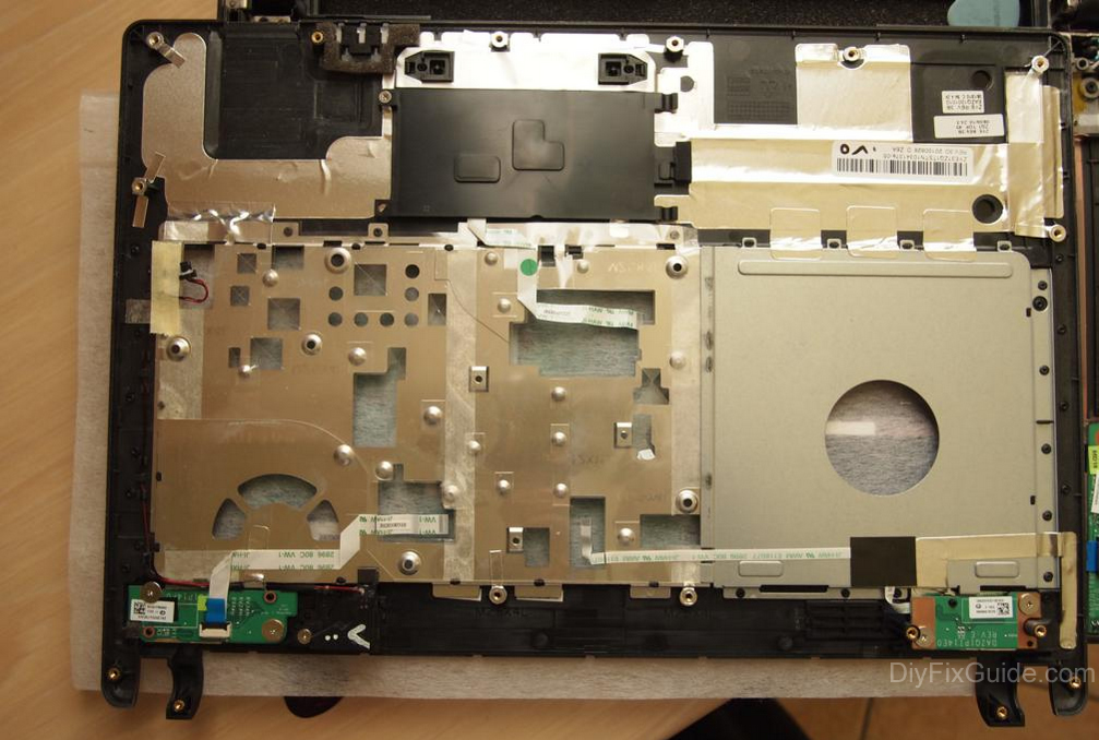
The only thing to do is insert a spacer between the top and bottom covers. I use my usual guitar picks.
I’ve marked some joints that need to be pushed in the photo below.
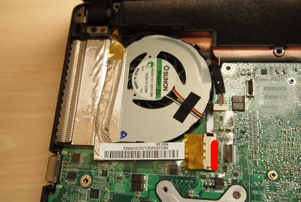
Step 7
Removing the motherboard
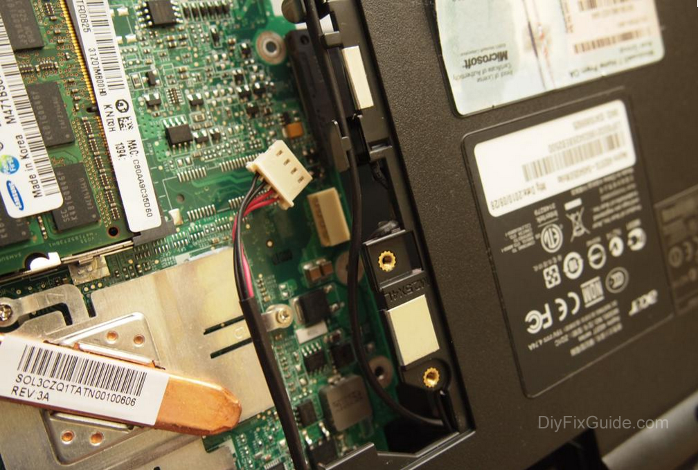
The motherboard is held in place by only two screws.
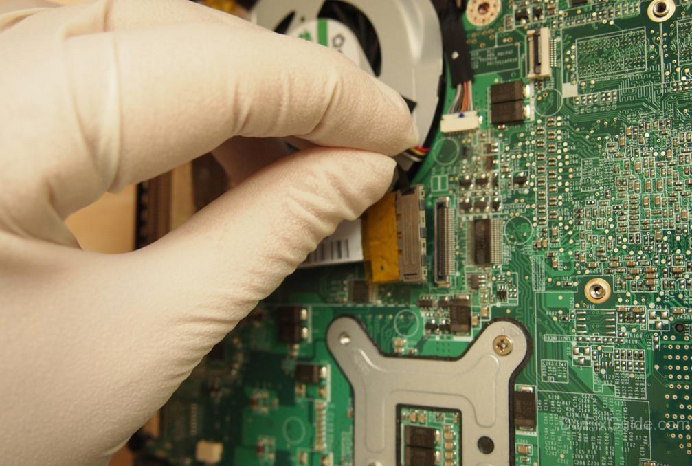
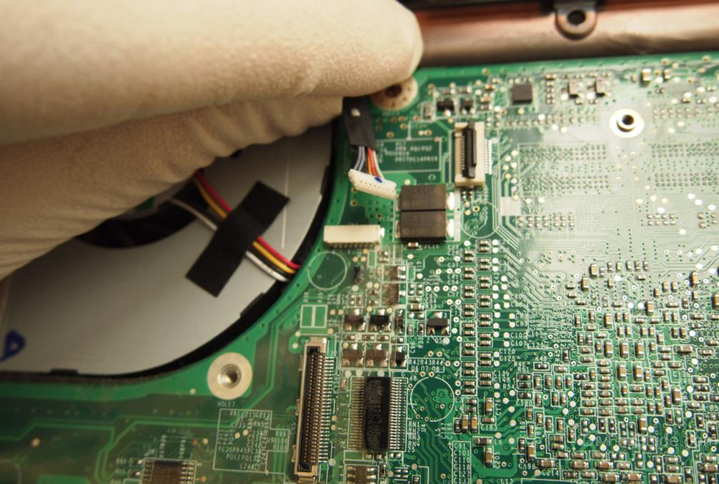
But first, you need to disconnect the cable from the connector.
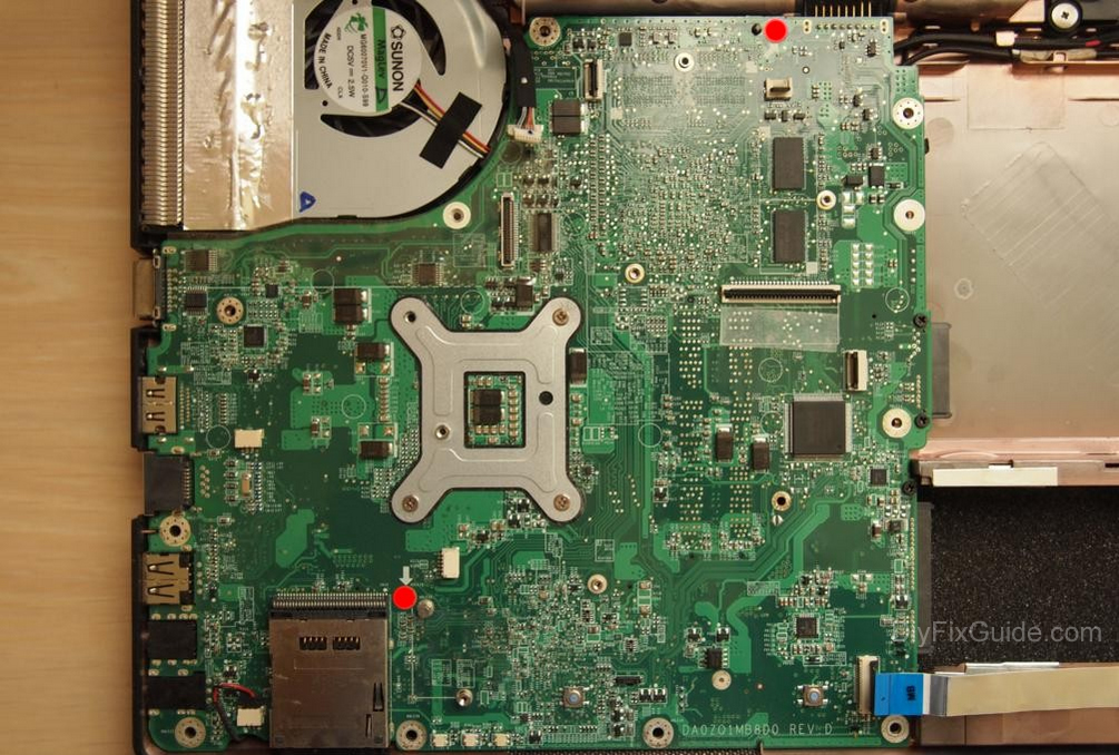
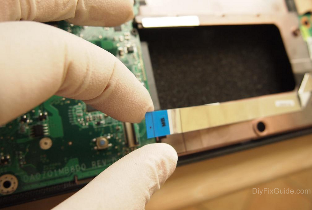
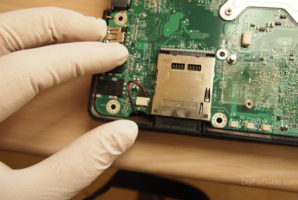
At this point, simply lift the motherboard from the right side, and it will come off easily.
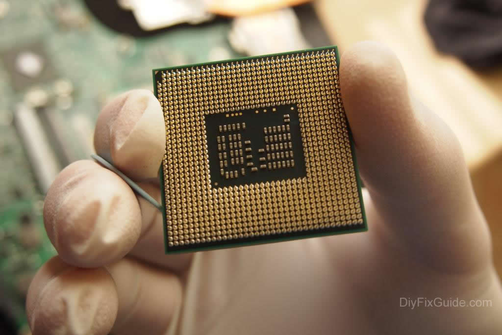
Step 8
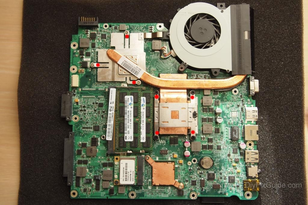
Removing the CPU
The CPU and GPU share the same heat sink, so we will need to unscrew all the screws that hold it in place.
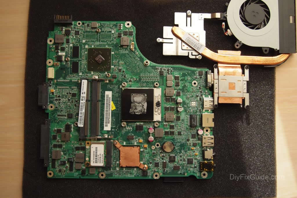
To remove the CPU (which may be upgraded to an Intel i5 or i7), you have to turn the black screw on the socket counterclockwise.
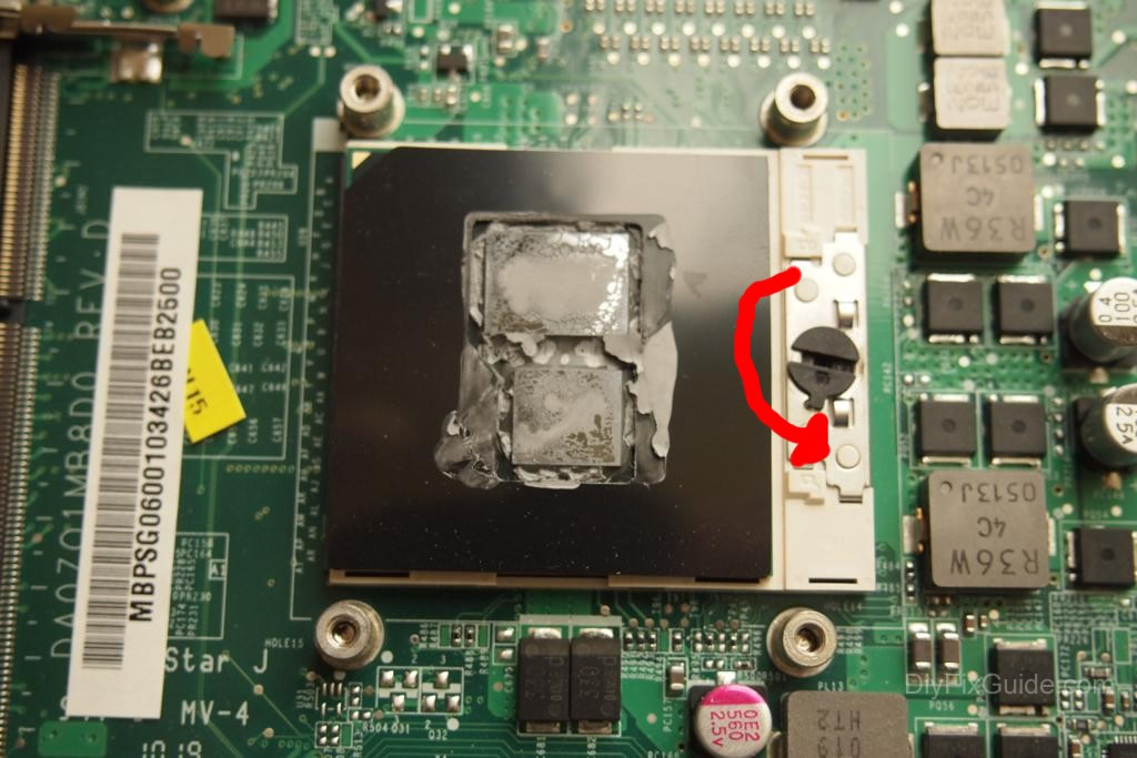
At this point, you can remove the CPU.